
vincen47
-
Content count
297 -
Joined
-
Last visited
-
Days Won
19
Posts posted by vincen47
-
-
Next up, I’ll add the frame-mounted primary fuel filter, a common sight on these Cats. I took a fuel filter from a Italeri Series 60, with a scratch built frame mount and fuel lines.
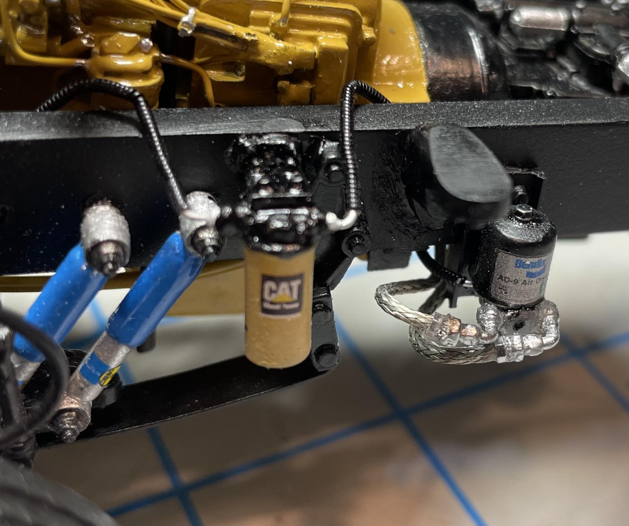
Just to the right of the cab mount, I added a Bendix AD-SP Air Dryer and associated connections and hoses. I started with an air dryer from CTM, and modified it a bit to better represent the Bendix model, and used decals from Modeltruckin for both the fuel filter and air dryer.
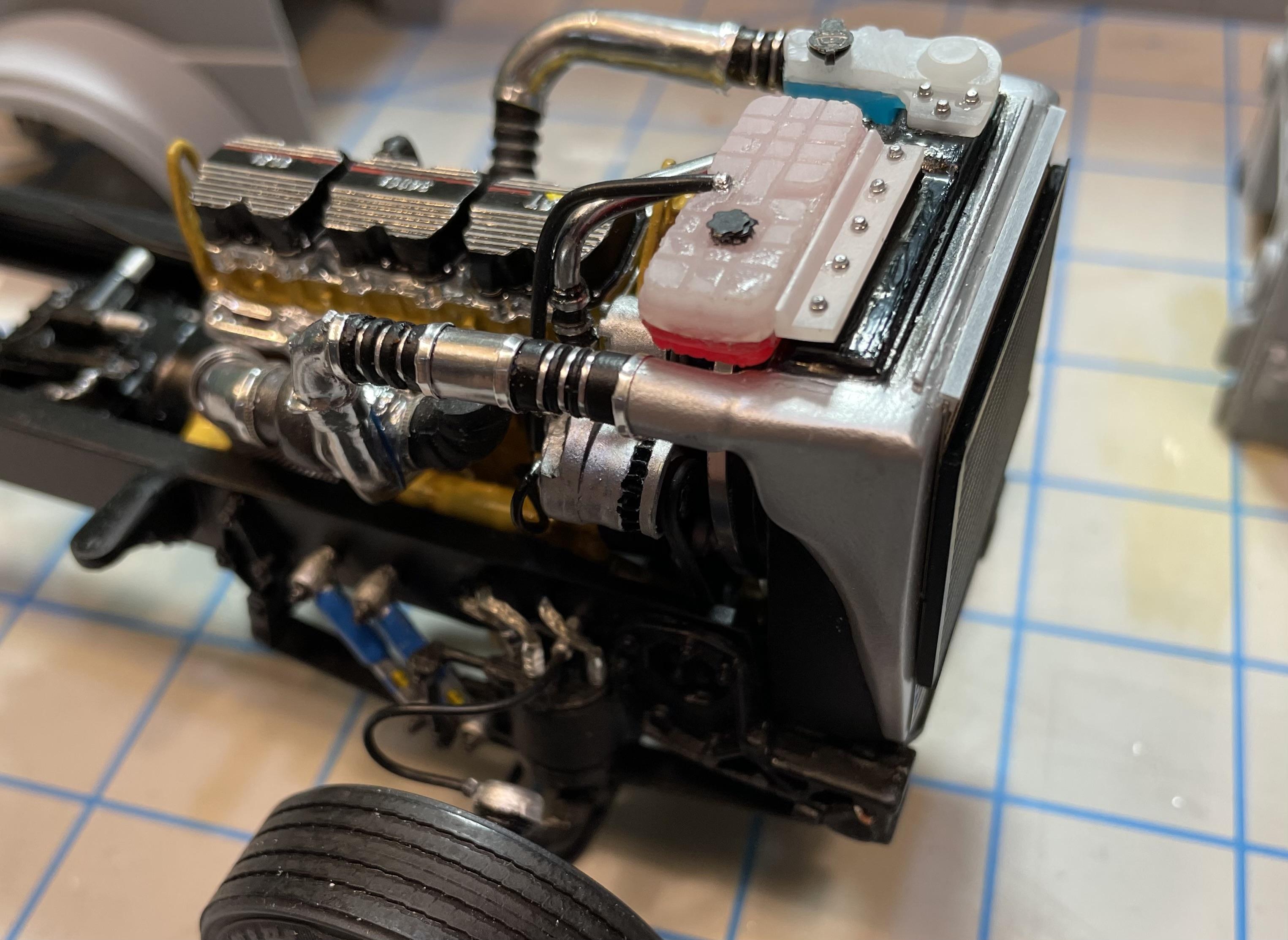
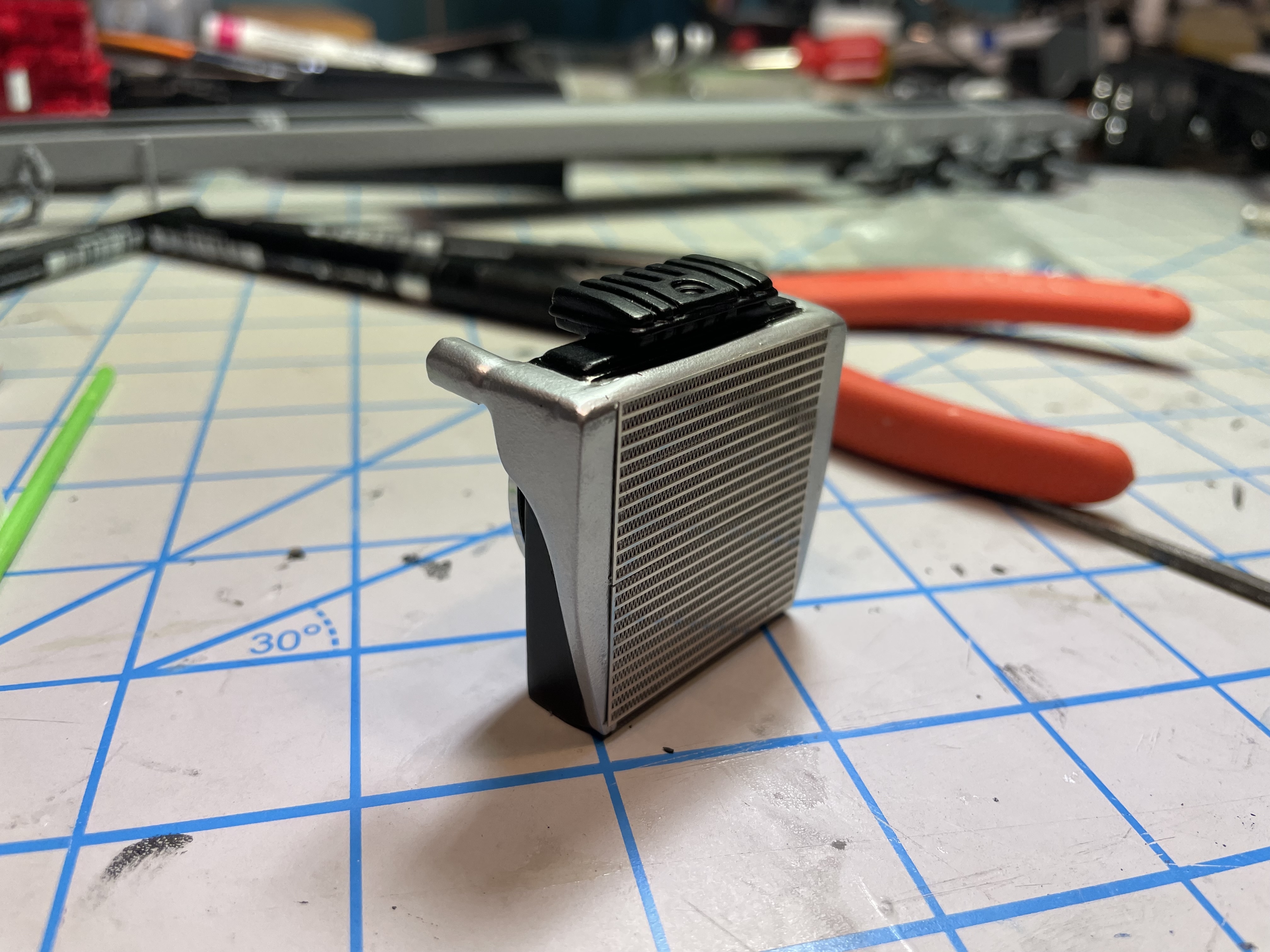
For the engine cooling system, I wanted something more on the lines of a modern-looking aftermarket coolant reservoir, rather than the Italeri kit’s radiator top tank I have on it in the earlier photos. The newer Paccar trucks, like the 389, 589, and W990, have something similar from the factory.

I started with the coolant tank from the A&N W990 kit, modifying and casting it in two halves. Using clear resin, the top half was tinted white to look like the slightly translucent white plastic, and the bottom half in translucent red. The long-life coolant used for these trucks is red, I’ve learned.
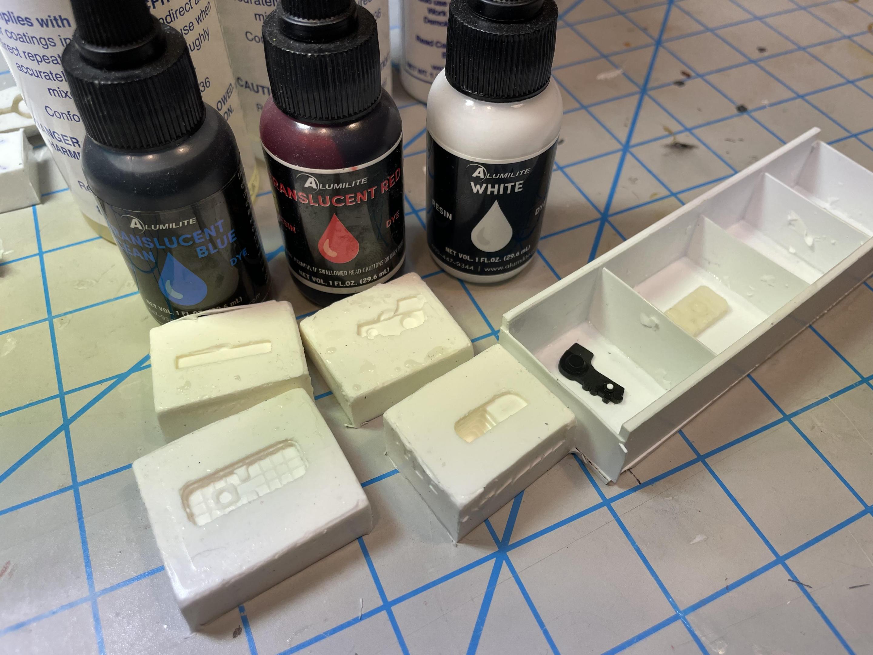
The unit is mounted to the top of the radiator with Tamiya bolt detail, and a photo-etched model car garage radiator cap tops it.
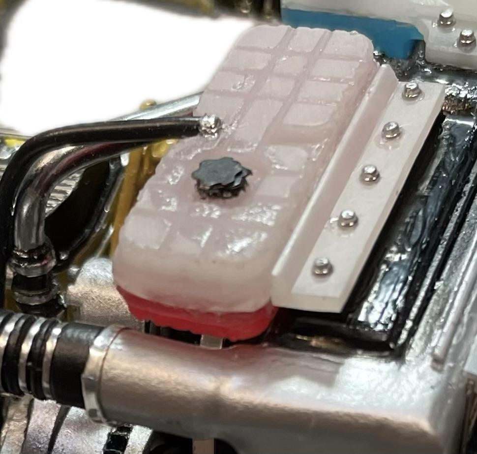
I made a windshield washer reservoir using a similar process, starting with the windshield washer tank from a modified resin casting of a Moebius Lonestar kit part for the bottom portion, tinted translucent blue. For the top portion and mount, I modified some unknown engine part from the parts box, cast in white-tinted clear resin.
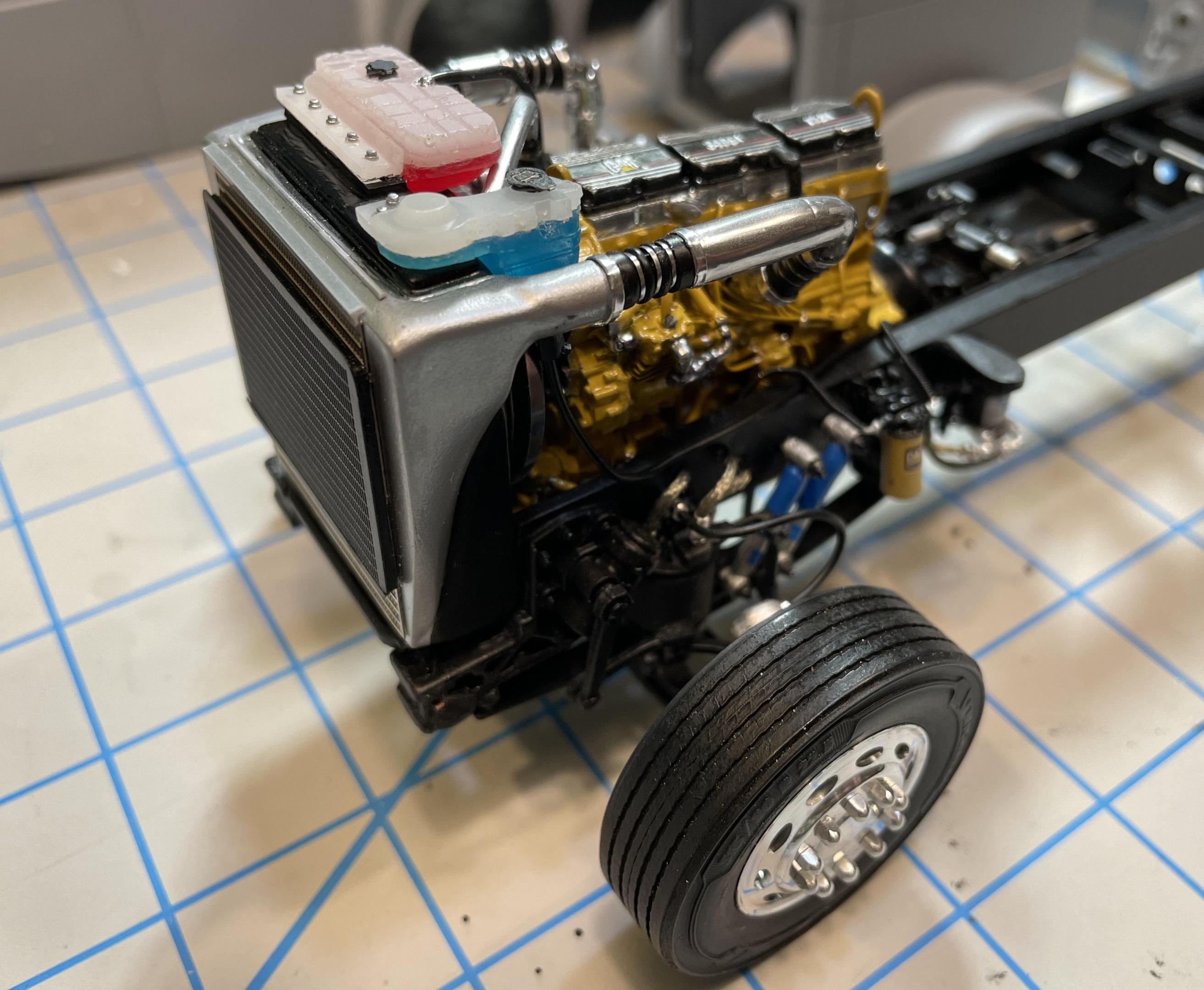
The chassis is basically complete, for now. More detail to add to the engine area once the hood is in place.
Next up, we’ll start the cab, hood, and coach body. Glad everyone is enjoying the build so far.
-
Yeah, you have a good thing started. Dark cherry will look good.
-
Nice builds, they look great. I like the color on the Mack and the Moebius wheels look great on the Dodge.
-
9 hours ago, Rbray47 said:Just found this forum while searching for parts. Hope to learn a thing or two. Just recently got back into building trucks.
Welcome to the forum!
-
Welcome to the forum. I have you saved as a favorite seller on eBay. Nice parts.
-
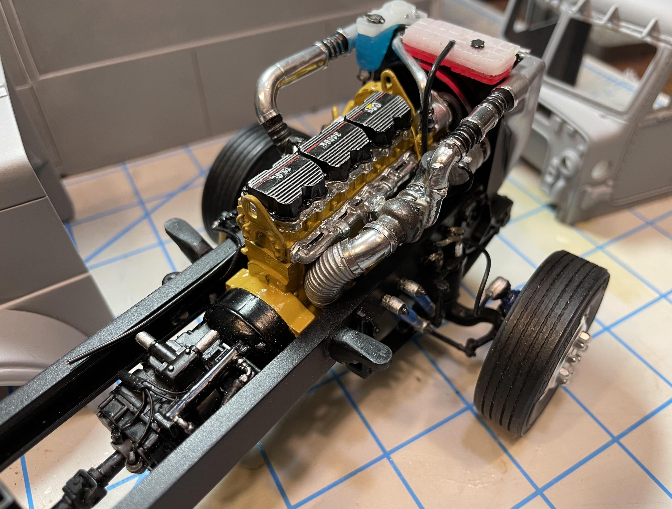
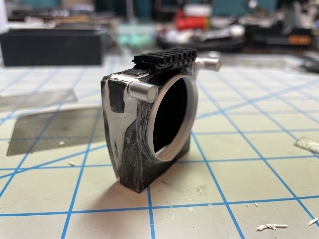
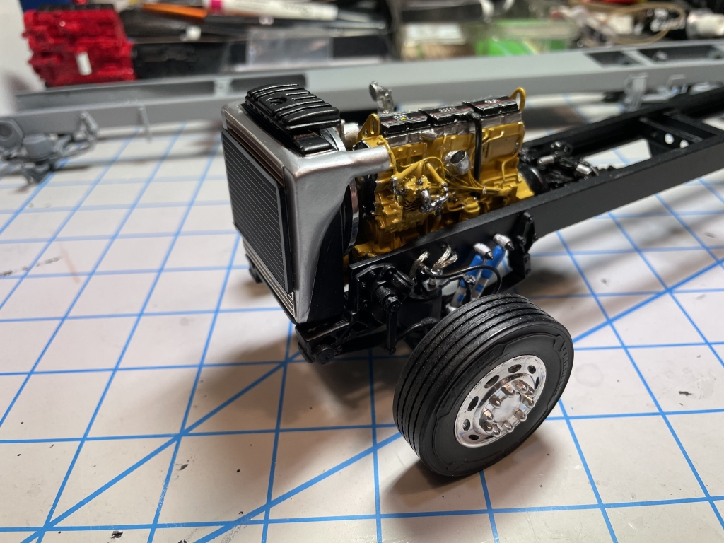
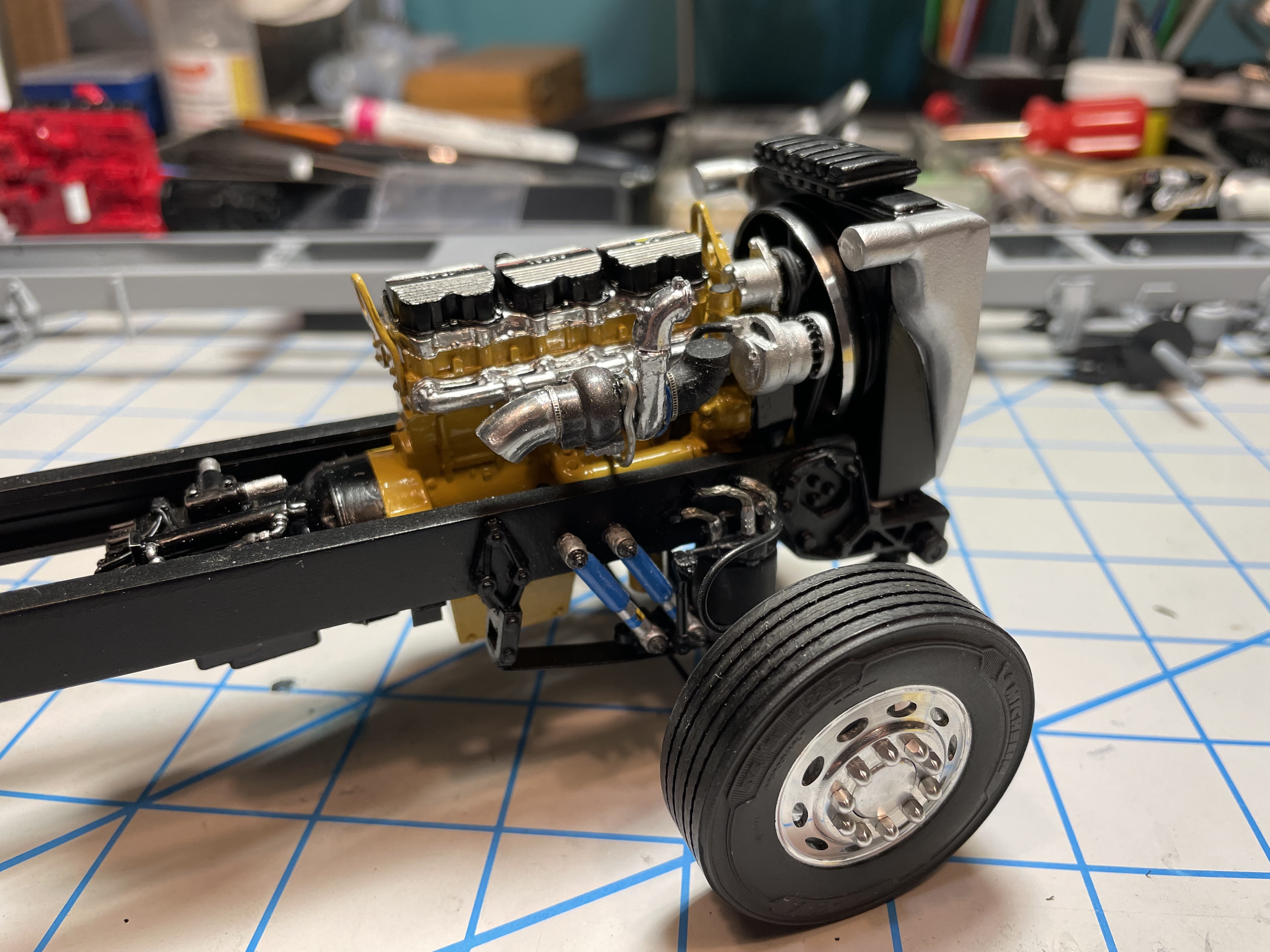
To connect the charge air cooler to the turbo and engine block, I used rubber air to air connectors from Moluminum along with Plastruct elbows and aluminum tubing, cut to fit and painted with Molotow chrome.
The rubber air connectors came in blue and orange, and though that’s common in real life, (orange on the hot side, blue on the cool side) I opted to paint them rubber black to better match the overall look. You can find black silicone connectors on 1:1 trucks as well.
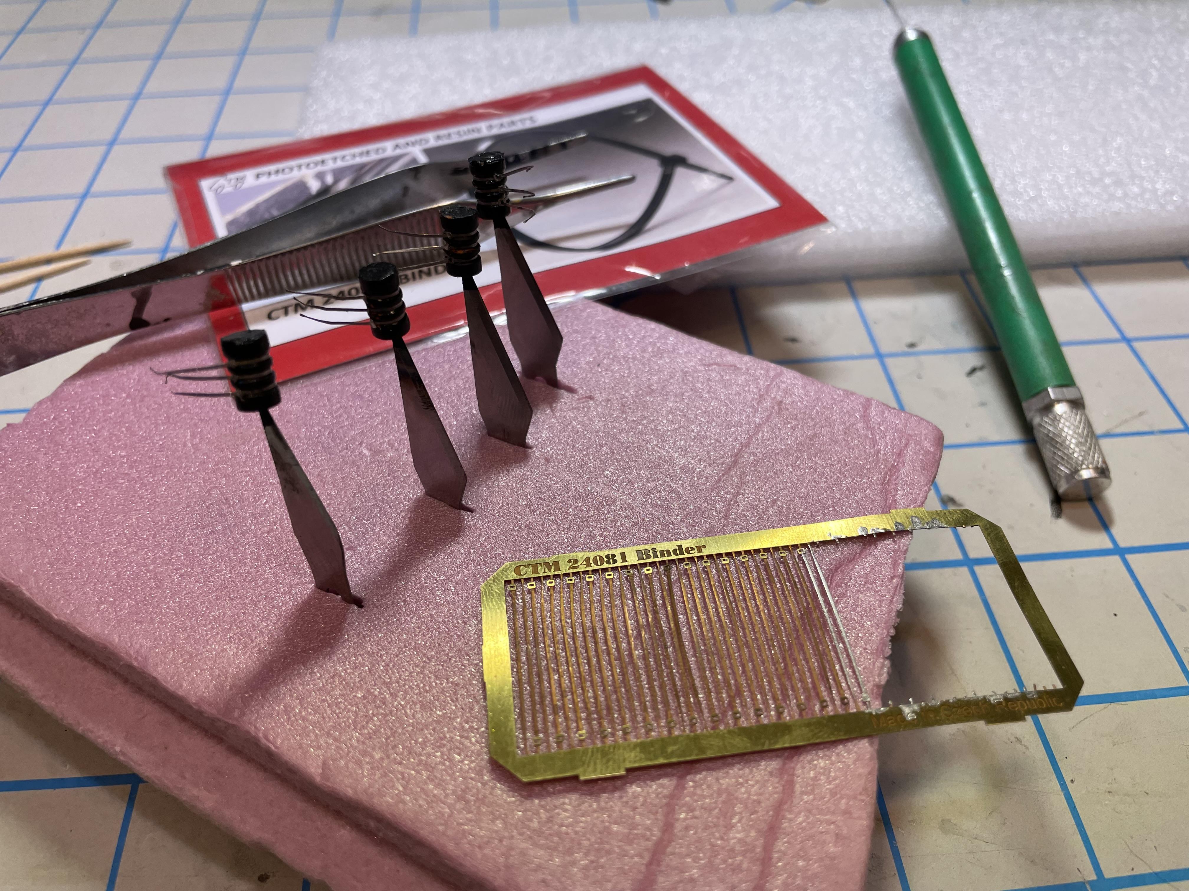
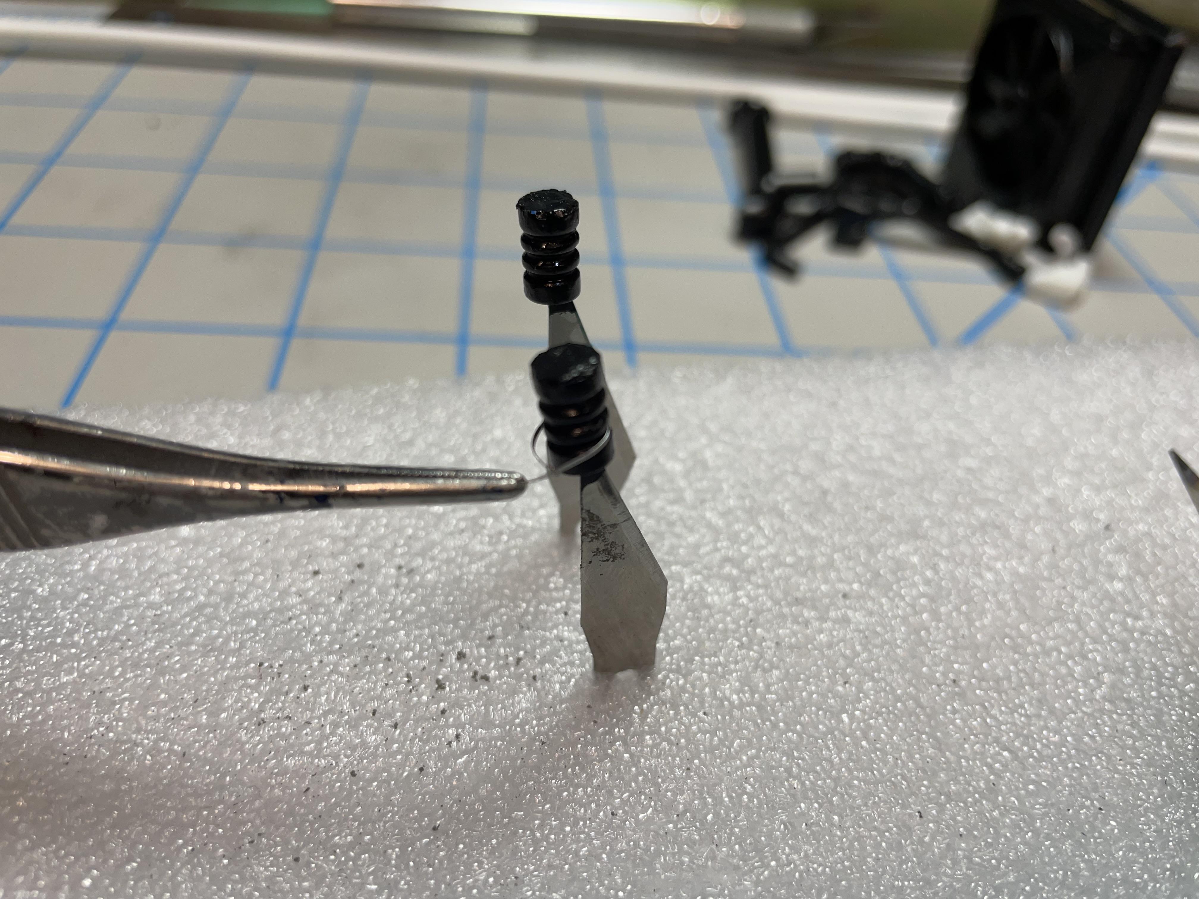
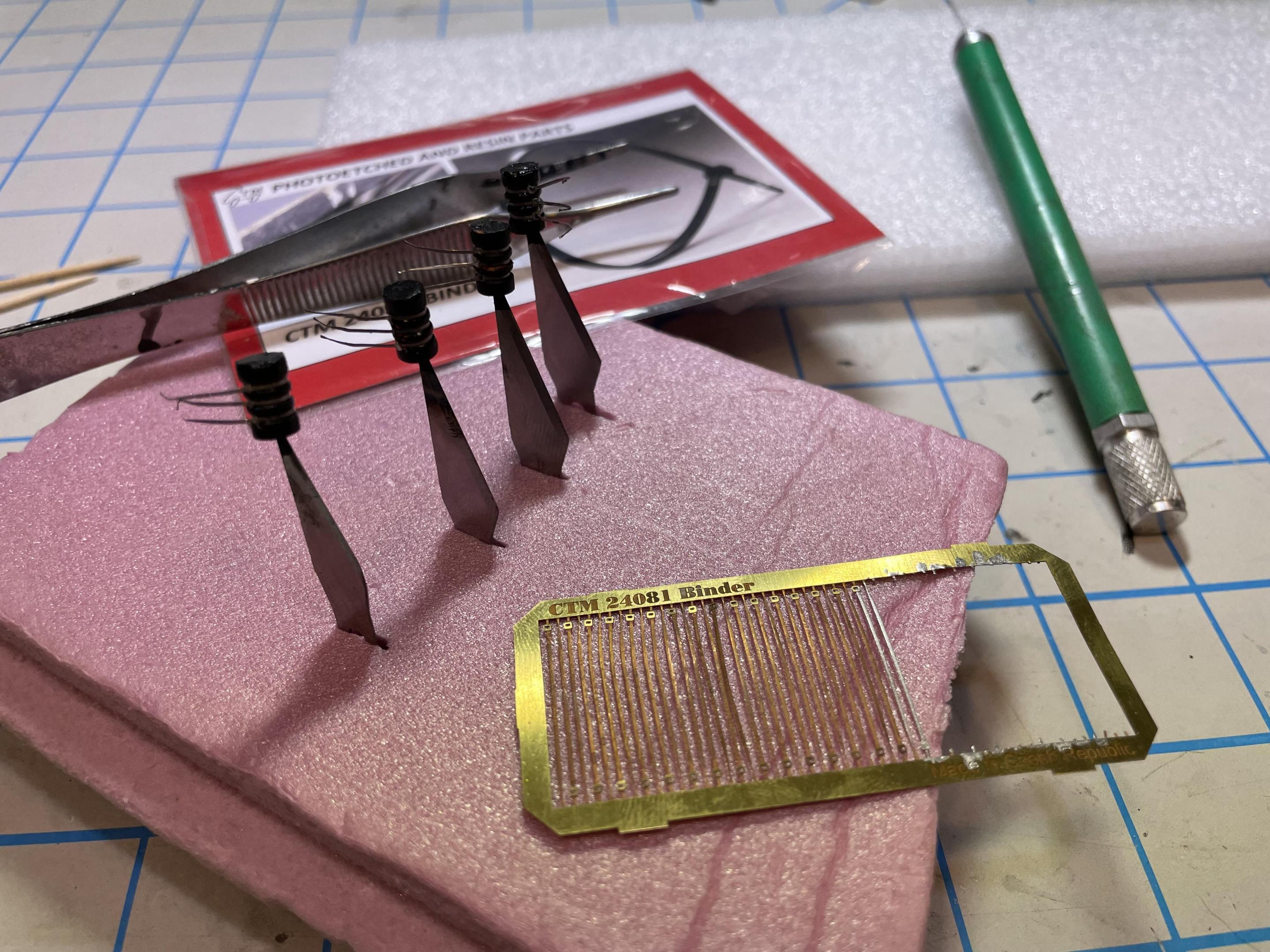 I also added the chrome rings around the connectors by using brass zip ties from CTM, painted chrome. That was one of the most tedious things I’ve done on this build, but the only option that seemed to work. Painting the recesses chrome was a failure, so CTM to the rescue.
For the exhaust exiting the turbo, I needed a flex tube, just like the real thing, in order to make the awkward curvature needed to fit between the engine block and frame. Once I had the plastic tubing bent to fit, I wrapped it in wire, and added putty between to get the look. Painted in aluminum, it works well.
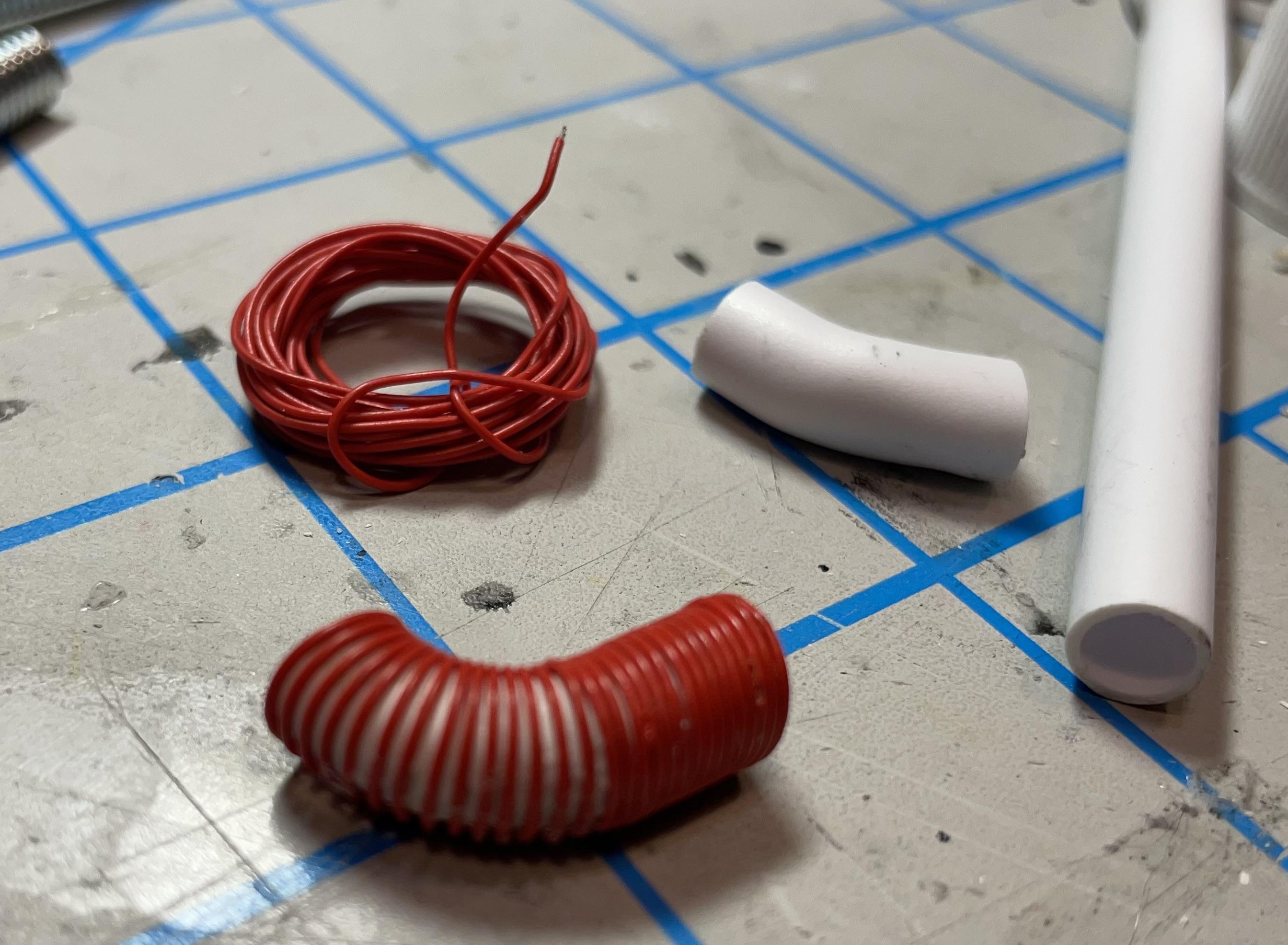
I finished with adding the tubing clamps where the connections are with chrome bands made from strips of furnace tape.
-
 1
1
-
-
Excellent job on a unique build.
-
35 minutes ago, Gary Chase said:Wow, man you got some serious skills, well done
Thanks, I appreciate that.
-
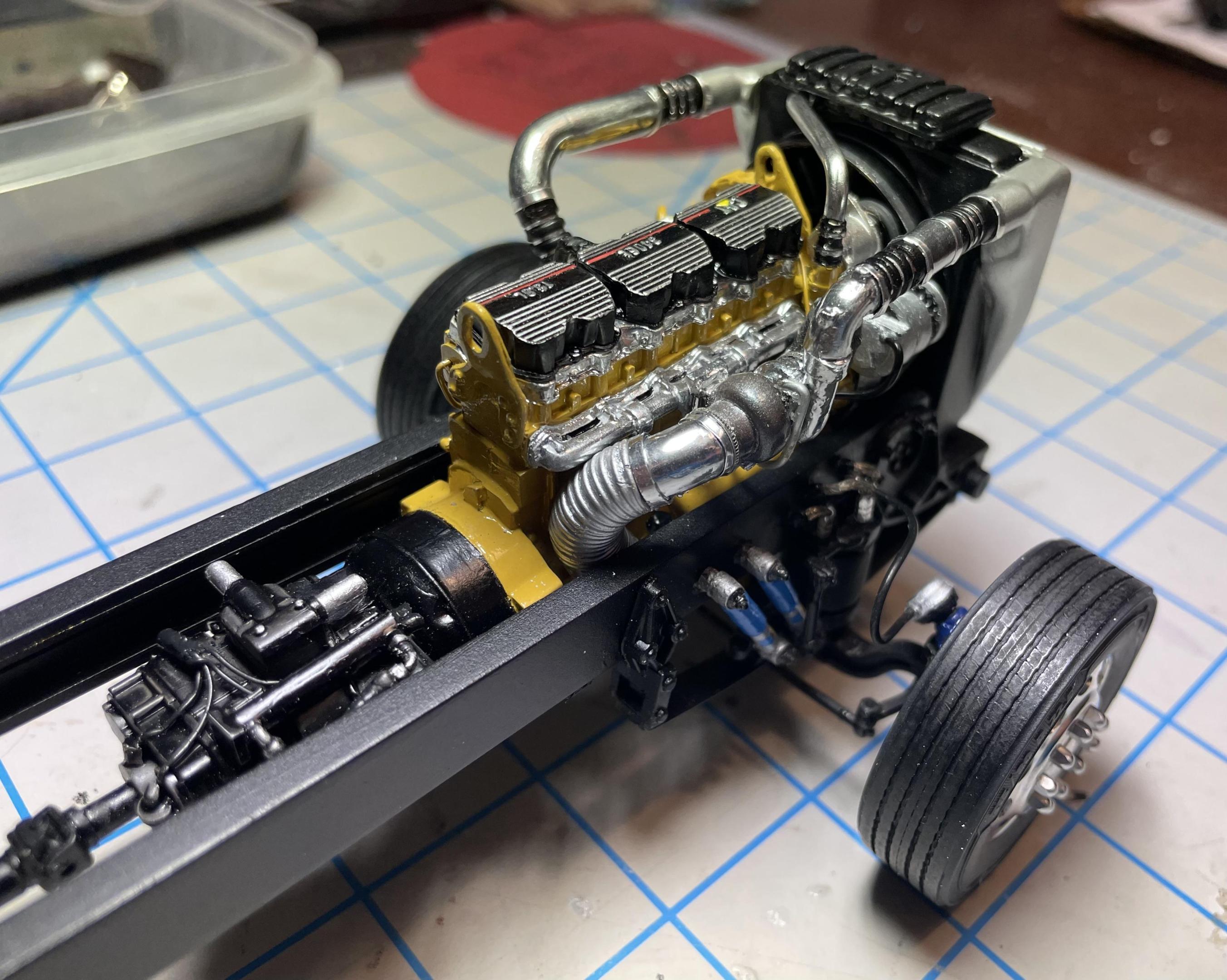
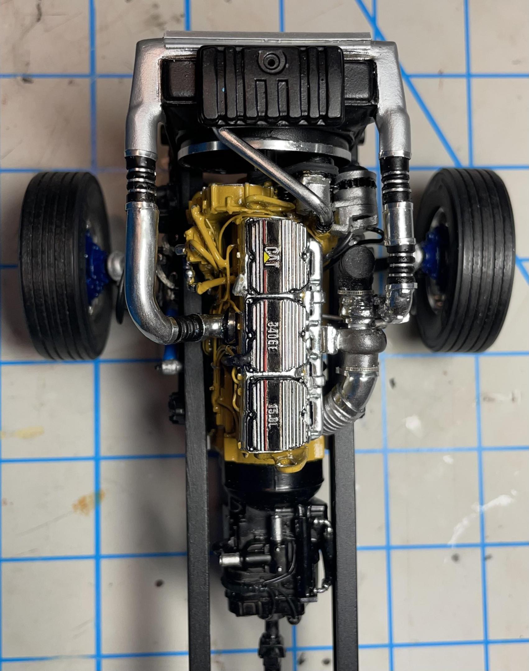
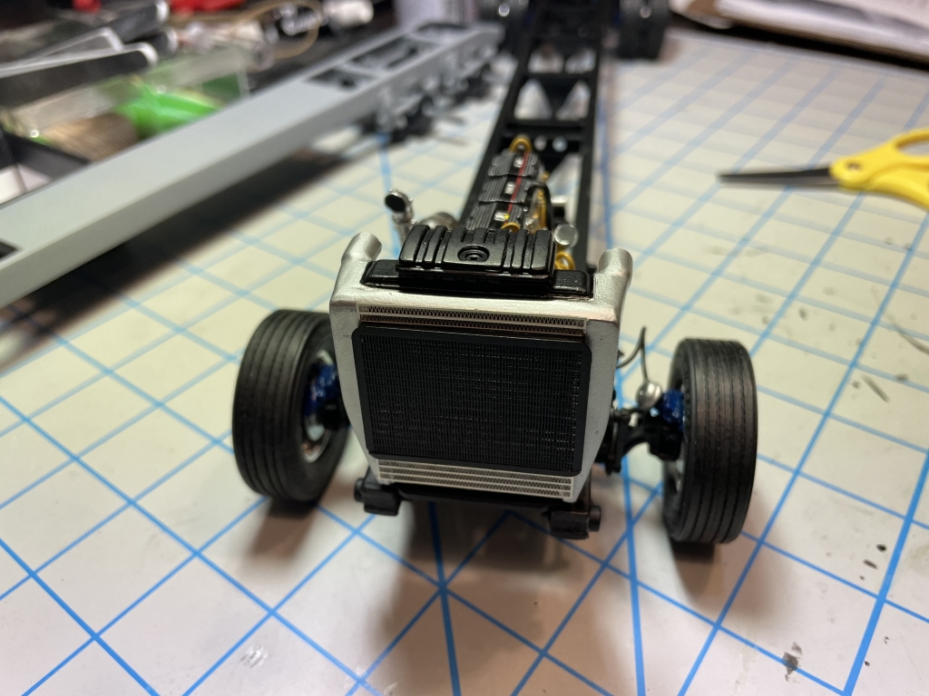
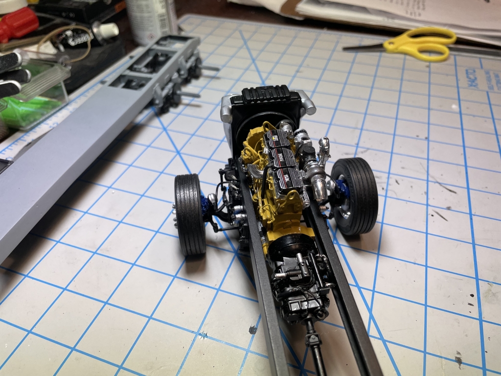
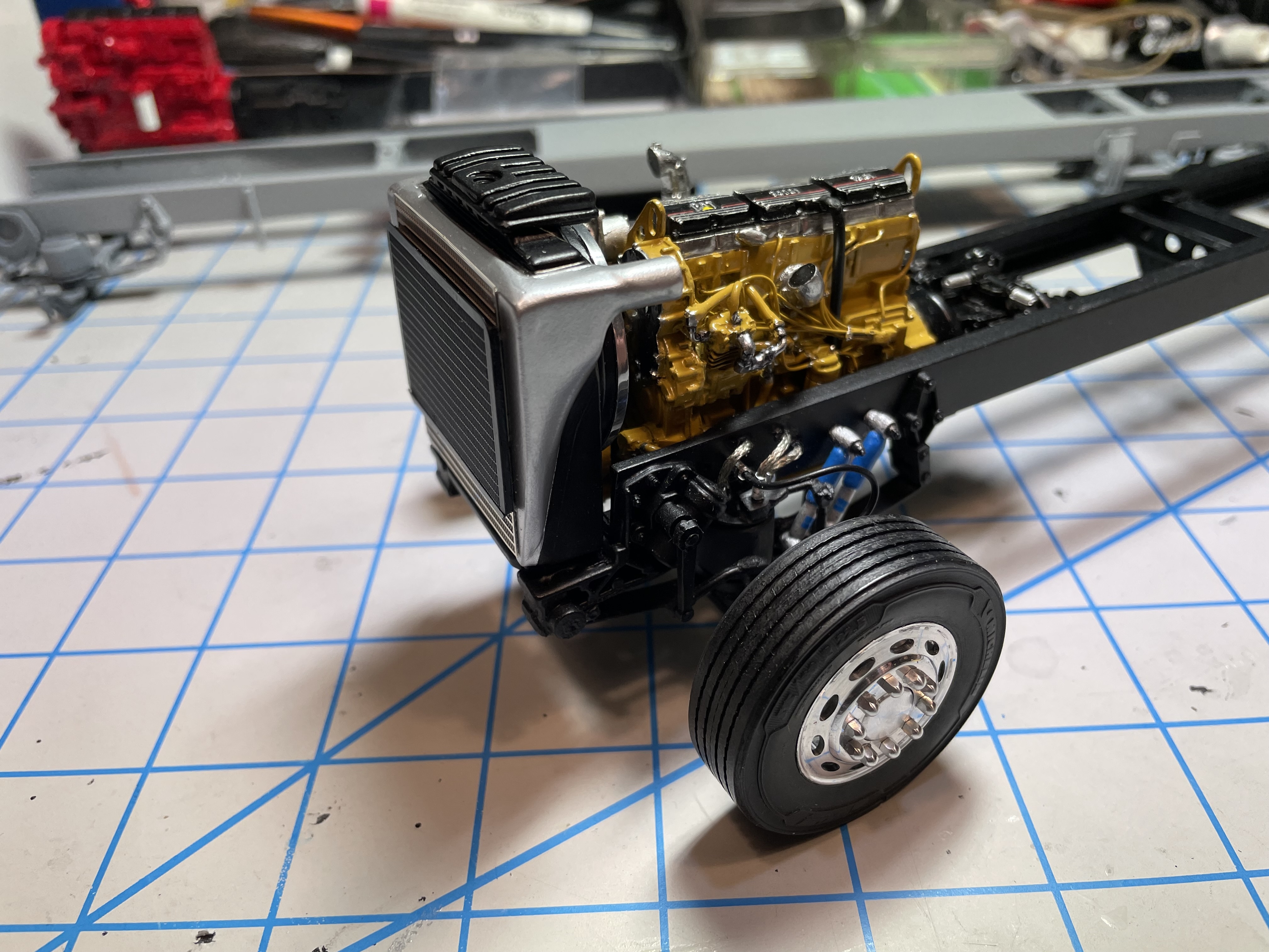
 Now that we have a rolling (non-rolling) chassis, time to install the engine and add the radiator and charge air cooler.

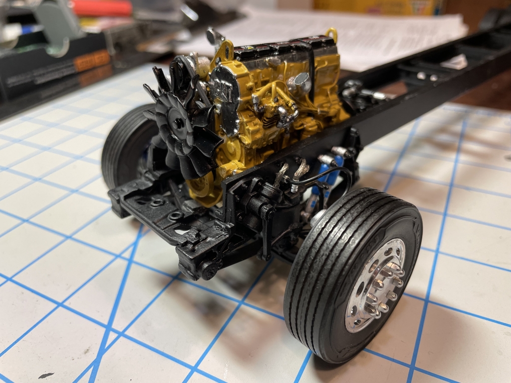 It’s a squeeze, but she fits. There’s a lot of extra parts adding to the overall engine width, like the serpentine bracket, so I made sure to measure and test fit beforehand.
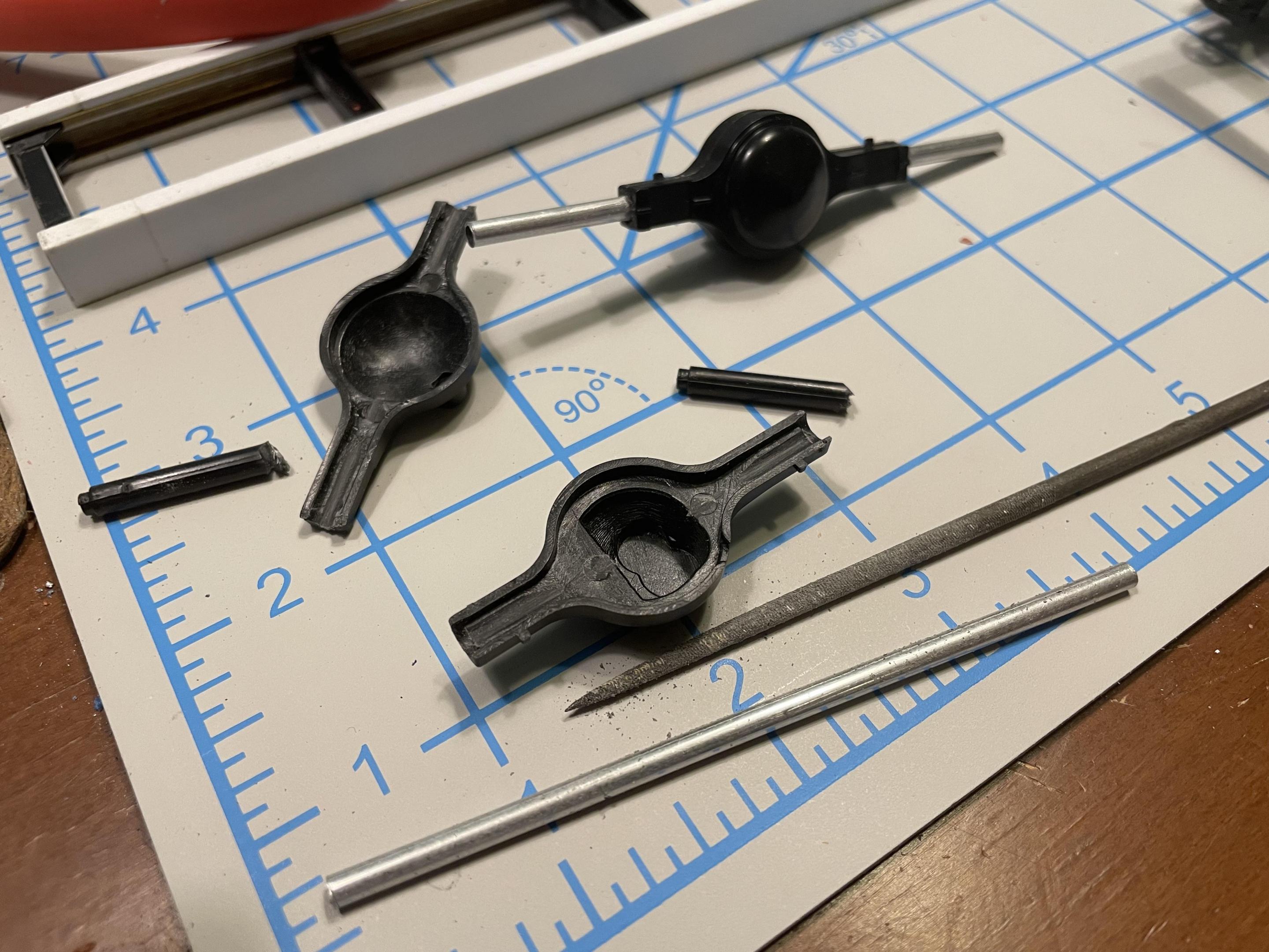
 To connect the driveline, I made three driveshaft carrier bearings from styrene.
Onto the CAC:
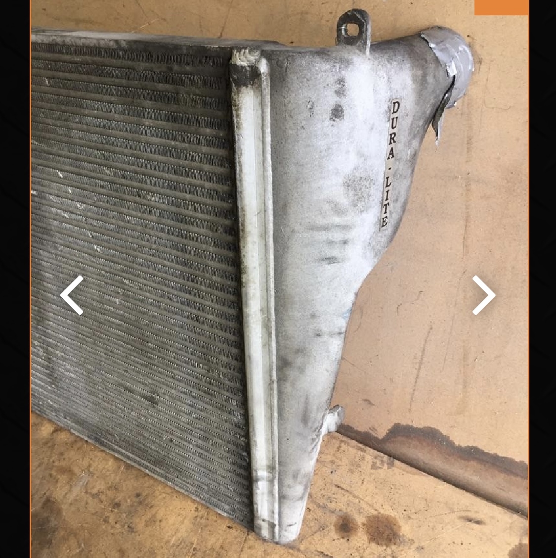
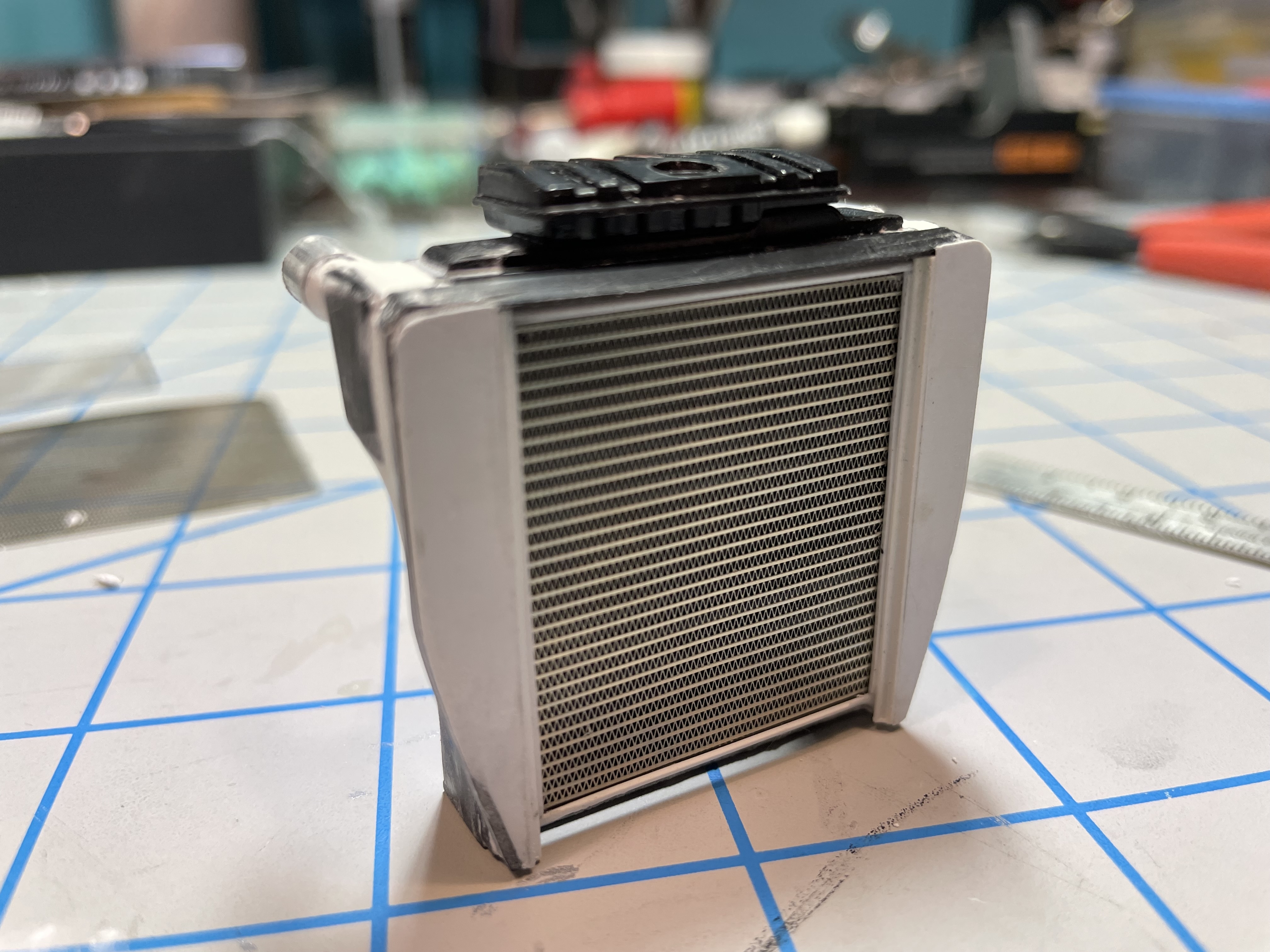
 There’s a void in the aftermarket for a proper charge air cooler/air to air aftercooler. Italeri tried in the 378 kit, but it leaves a lot to be desired. I used the Italeri kit parts as a basis for creating an aftermarket CAC in the style of a Duralite.
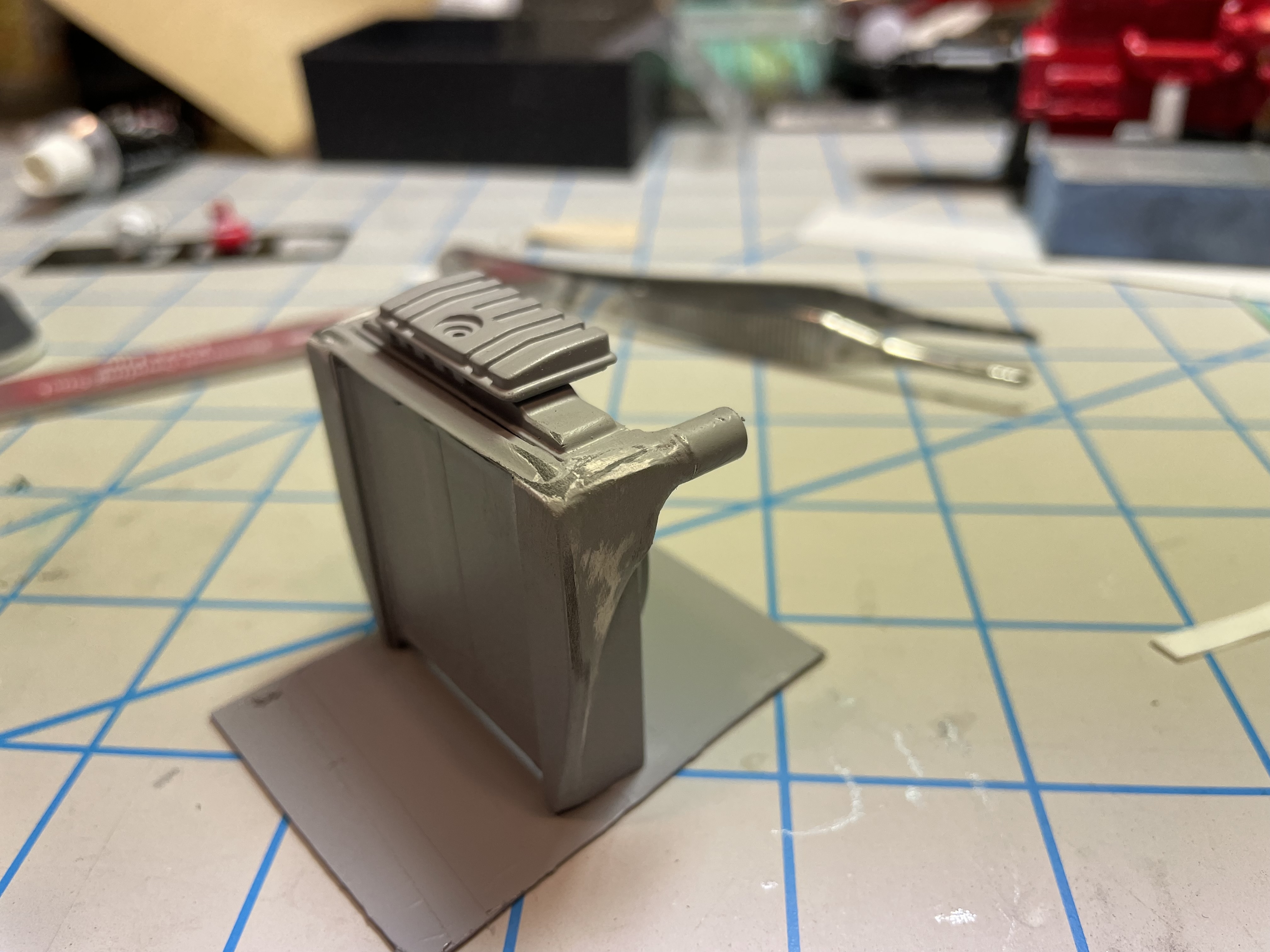
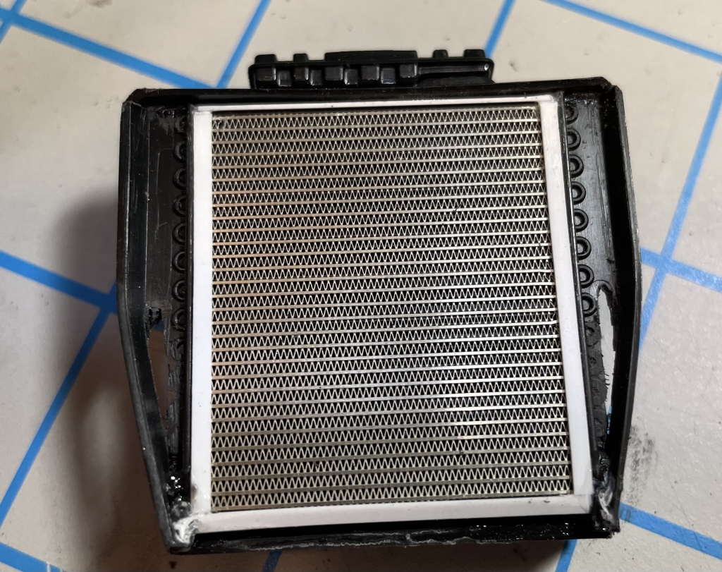 I added photo etched radiator mesh and modified the side of the kit radiator. Then, adding putty to create the shape needed. The kit’s radiator coolant reservoir was added to the top at this point, but I will replace it later with a better version.


 On the front side, I added a parallel flow AC condenser unit, made with photo etched mesh. I’ll add the lines to and from it later, as well as the air intake connectors and pipes to the turbo and engine block.

-
1
-
-
It would be a great model if it was fully static, but the fact that it has a functional boom and outriggers is extra impressive. What’s under the hood?
-
That’ll be an awesome build.
-
Beautiful paint colors, and details. Impressive scratchbuilding. Love the subject and craftsmanship.
-
2
-
-
Wow, fantastic build. 103k? She’s certainly heavy. But I suppose that adds stability. Nice scratch building. She’s a beauty.
-
1
-
-
Wheels and Tires…
Most 1:1 RVs of this size are running 315 (or larger) tires, especially in the steer position. The hobby market, in my opinion, is lacking in accurate big rig tire offerings - don’t get me started on the generic junk that comes in kits that look more like 1:1 all-position retreads than anything else…
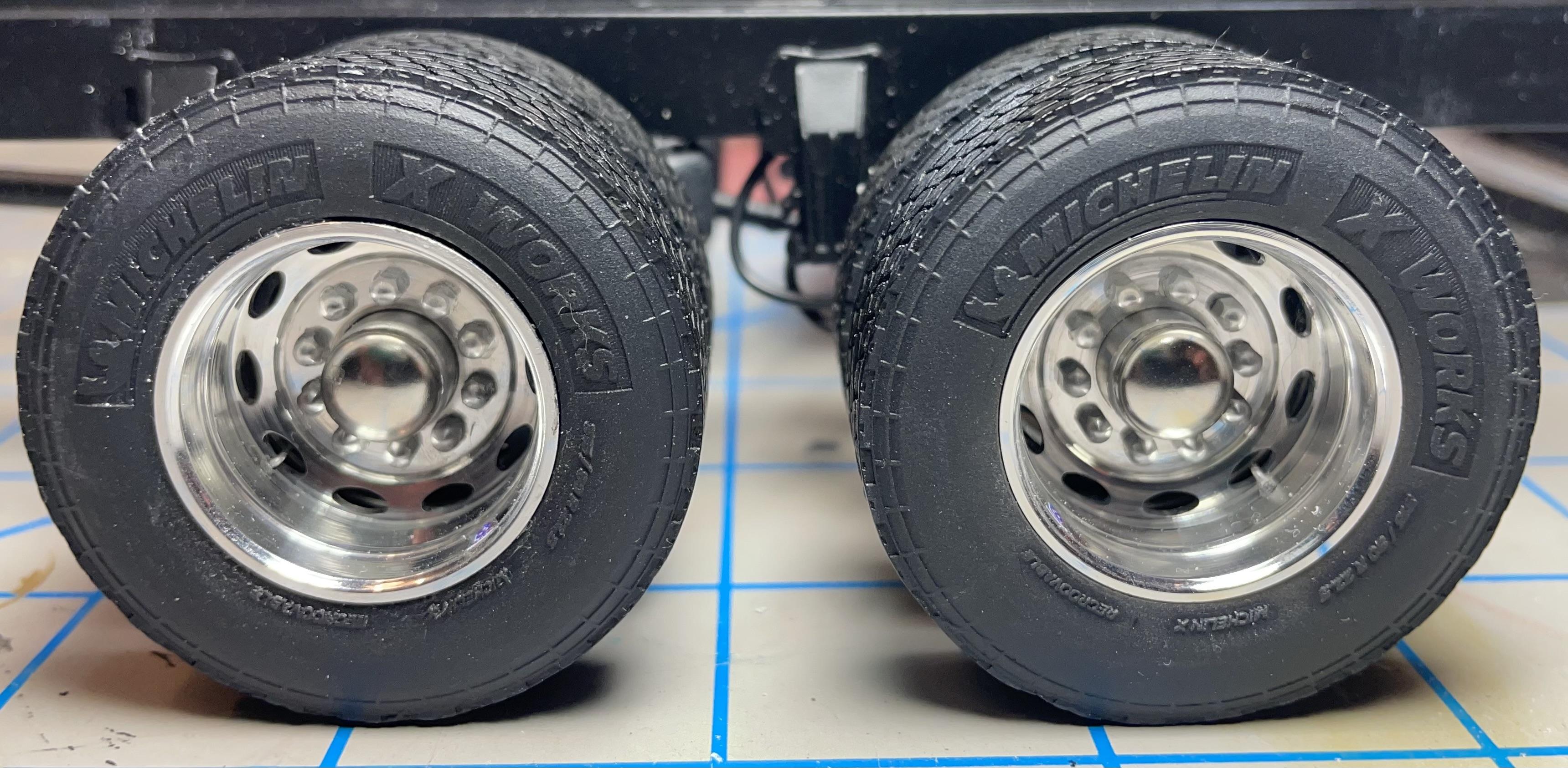
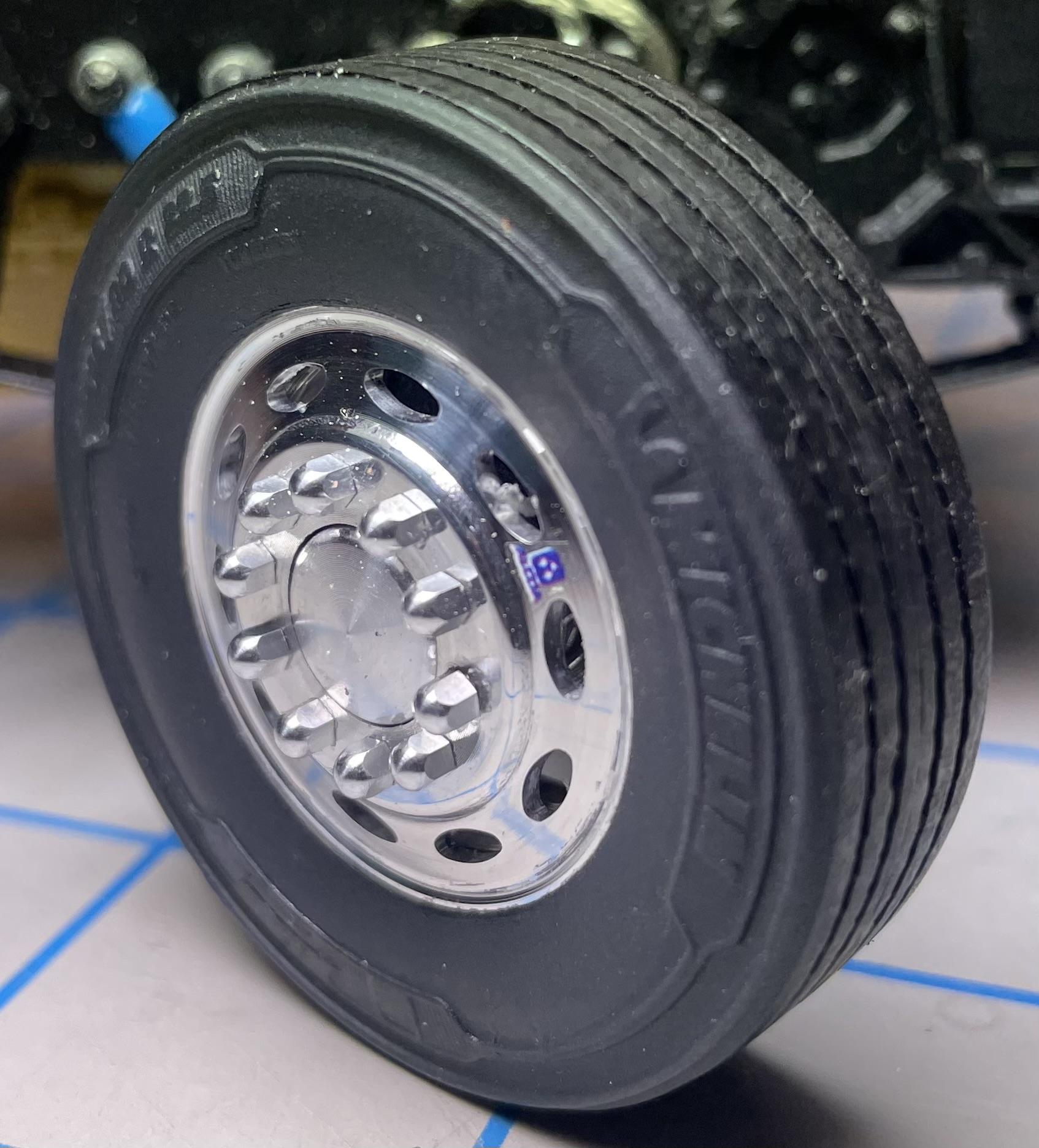
So, I searched for a very long time, waiting for detailed, modern tires that would be accurate for the build. A&N Resin came to the rescue when they introduced the perfect tires - Michelin X-Line Energy Z Coach 315/80r22.5 Steers and X-Works 315/80r22.5 Drive tires. Incredibly detailed. On their website they list them with more generic names like “highway tread standard width front tire” etc.
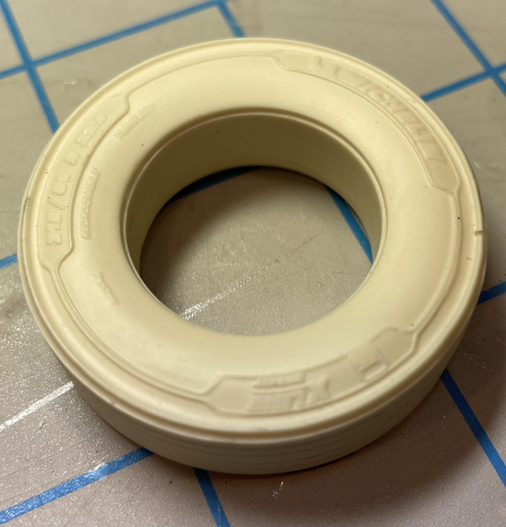
At first, I was disappointed they were only available in hard resin, but that turned out to be a blessing as they’d support the weight. I now prefer hard resin tires for their detail and strength. Painted with Tamiya Rubber Black, they look the part.
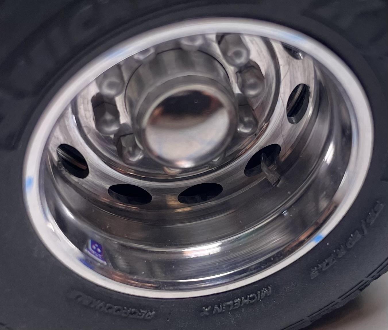
The wheels are real aluminum Peterbilt Oval Alcoas from Keystone Aluminum Model Miniatures. Unfortunately, he’s no longer around, but M&R offers great wheels nearly identical to these.
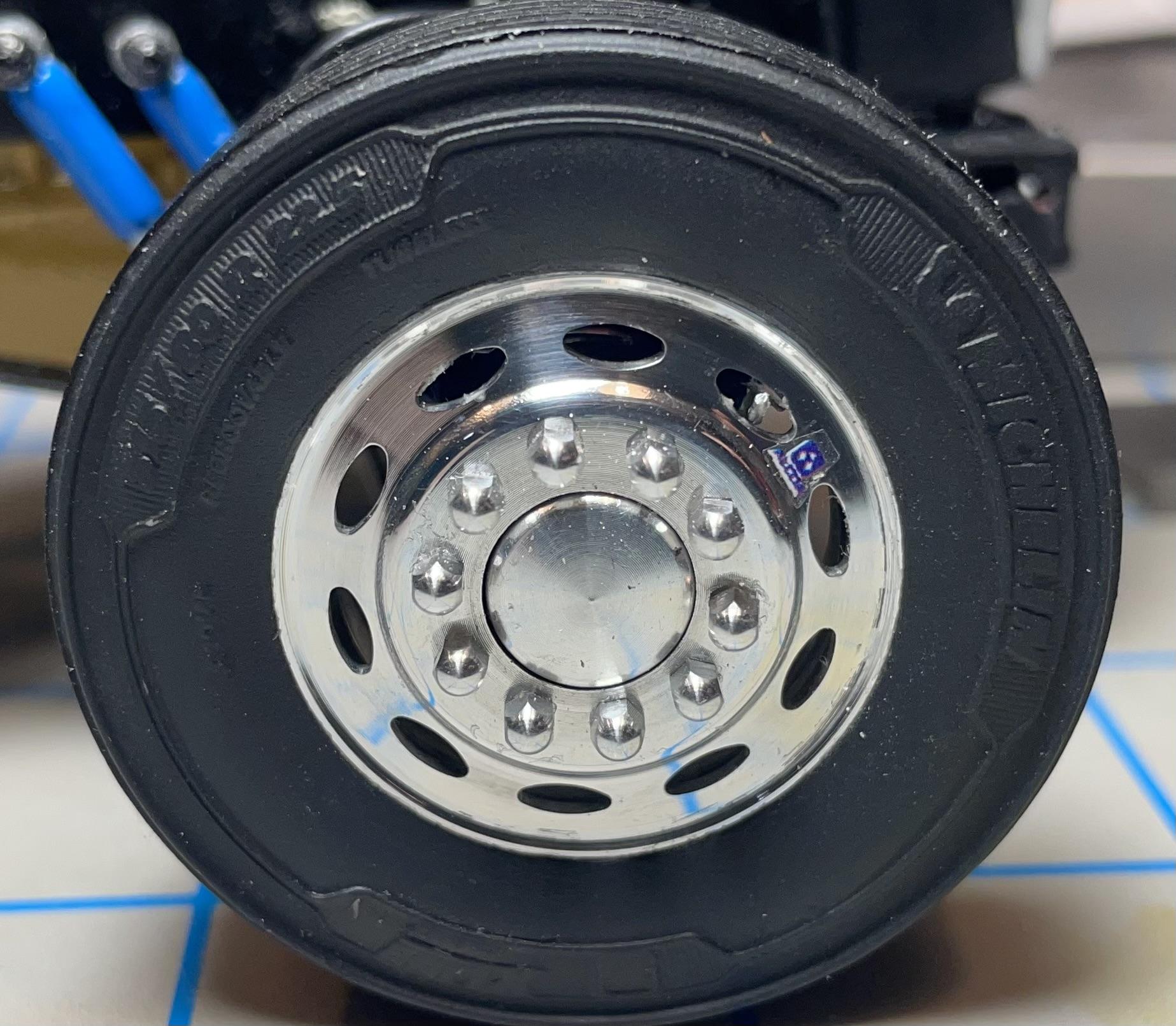
The rims fit the M&R hubs perfectly. However, the A&N tires had to be sanded out larger to accommodate the one-piece wheels. Not a fun thing to do. I used sand paper wrapped around a broom handle, gradually adding layers of paper. 10 tires took a while, as you can imagine.I also had to add a spacer between the rims on the rear axles to accommodate the wider tires. I used simple 8mm washers from the hardware store. Because the rims now sat further out on the hub, the top hats looked a little short. So, I added 8mm hubcaps from Auslowe. They fit perfectly and even have a better rounded profile than the original M&R hub.
I detailed them by adding Acorn nuts from Keystone, Alcoa decals from Model Truckin’ and scratch-made valve stems from Detail Master #1 line and fittings. Tedious, but worth it.
I don’t think I took any photos of the rims before I mounted the tires. Wish I had.
The outside rear wheels have inside-facing valve stems, just like they so on real trucks.
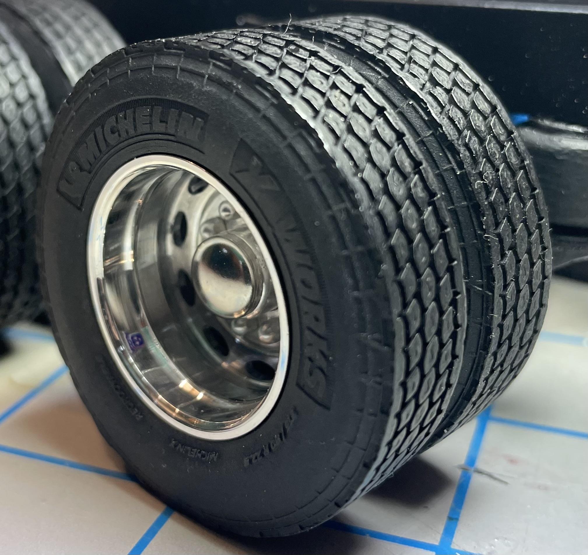
The tread and sidewall detail is fantastic on these tires. They are geared towards the Euro truck market where it’s more common to run 315s in line haul service, but it’s great having the option here in the U.S. for a unique build like this one, and others that need a little more beefier tires.
A&N also offers heavier tread pattern 315s, along with 385s for highway tread steer, heavy tread steer, and drive treads, for your North American fire, construction, and logging equipment needs. They also have resin wheels designed to easily fit their tires.
-
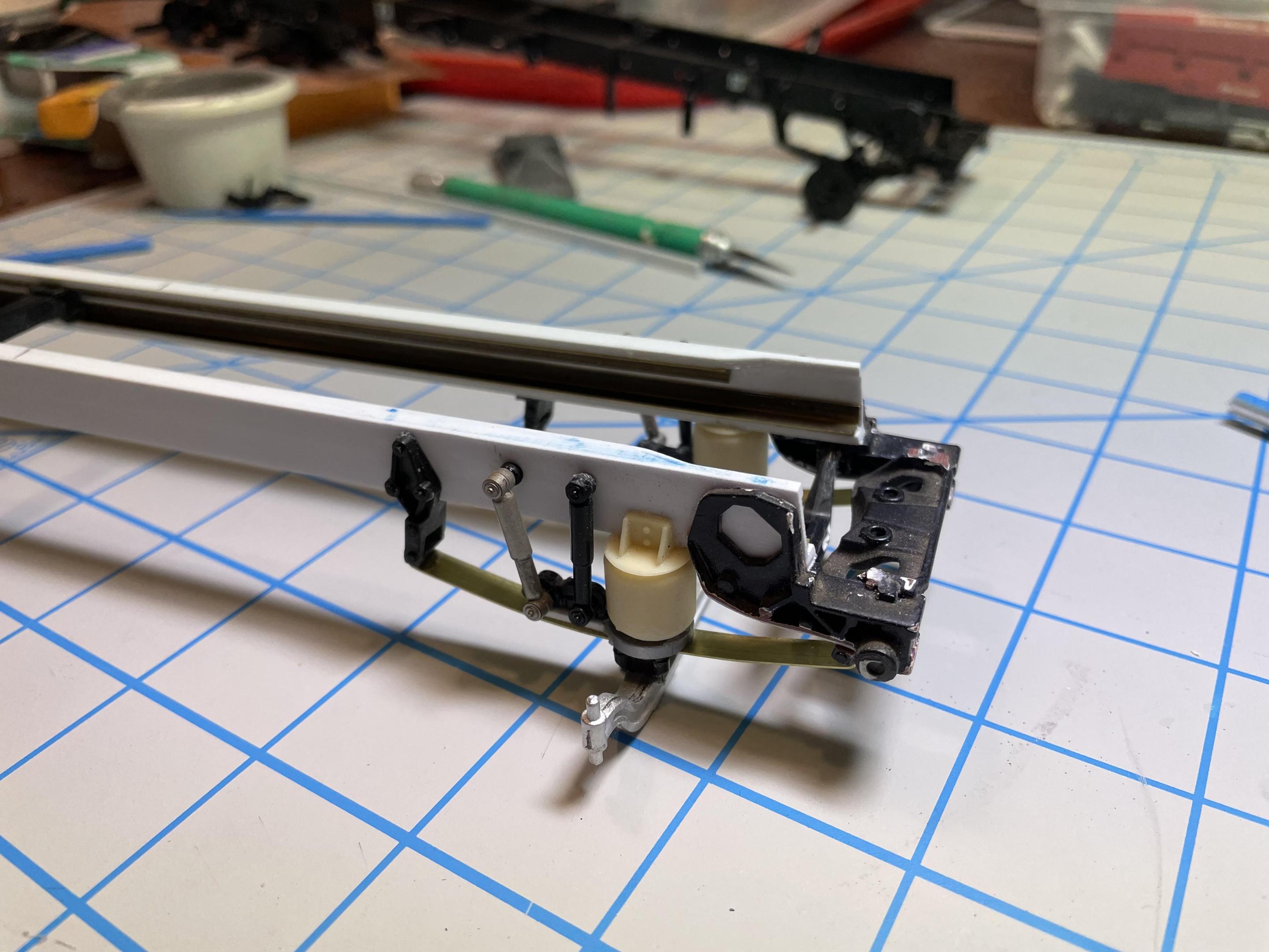
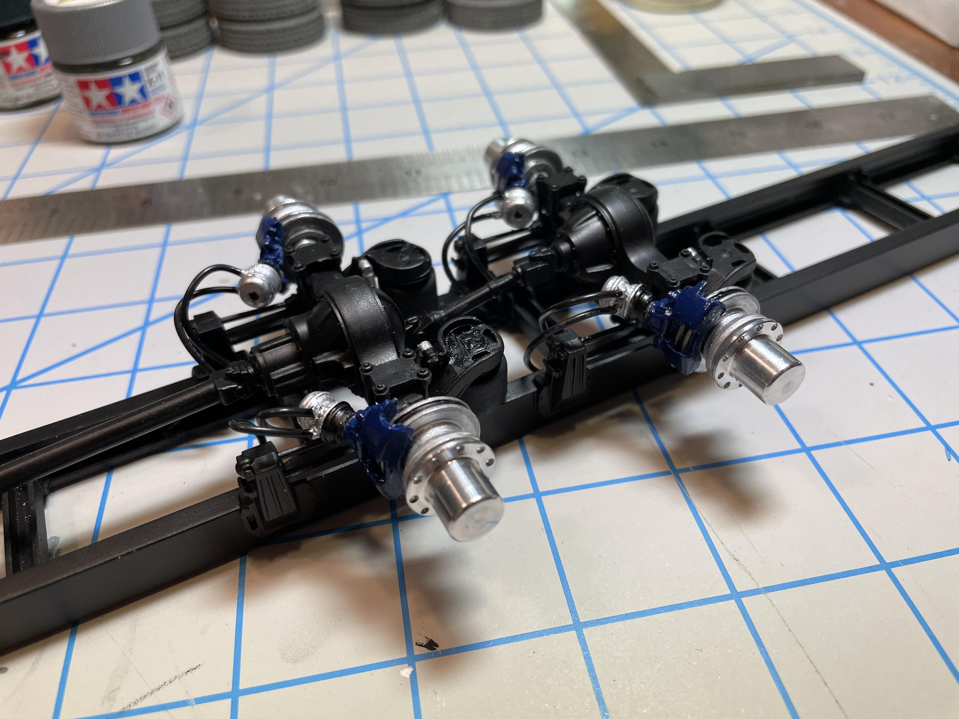
Now onto the rear axles, suspension, hubs and brakes. The main chassis color is Tamiya Semi Gloss Black. There’s a couple other shades of black, and also Tamiya Rubber Black (a very realistic color) used on the air bags.
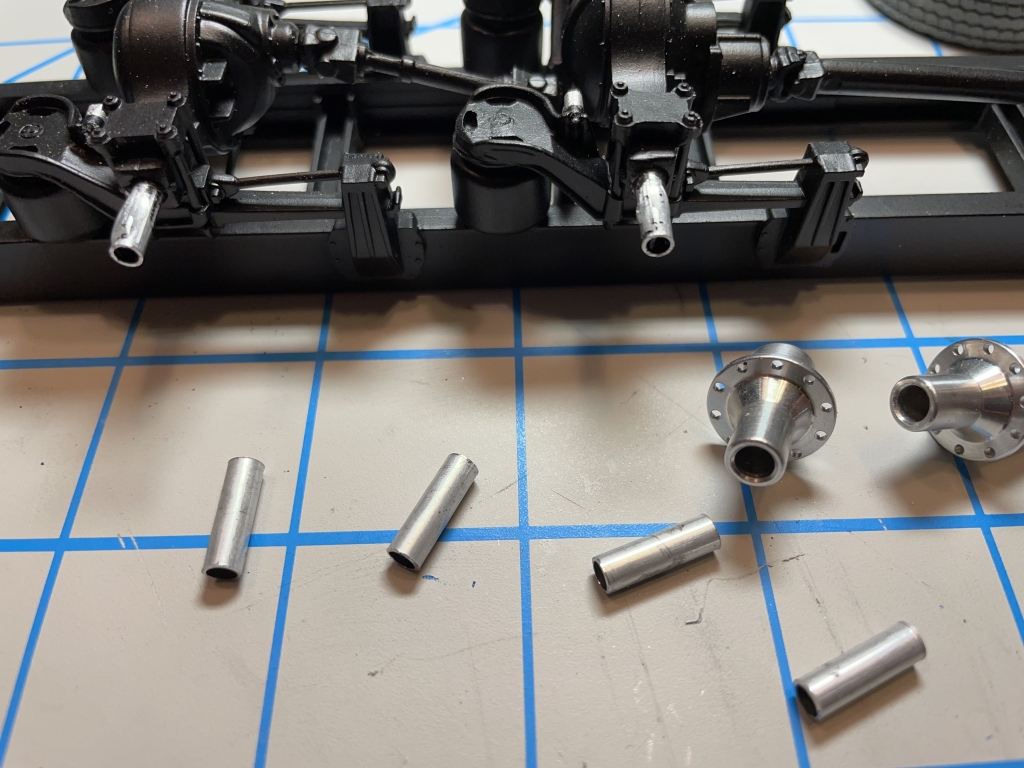
The rear axles needed a sleeve of wider tubing to fit the wheel hubs. Those beautiful real aluminum hubs are from M&R Wheels. Highly recommended, they make excellent products.
I got the M&R hubs to go with the Keystone Aluminum Peterbilt Alcoa wheels, which are fantastic, but didn’t come with hubs with a socket for the axle stubs. I probably could have figured out a way to make the Keystone hubs work, but M&R provided a much simpler option. More about the wheels in a later post.
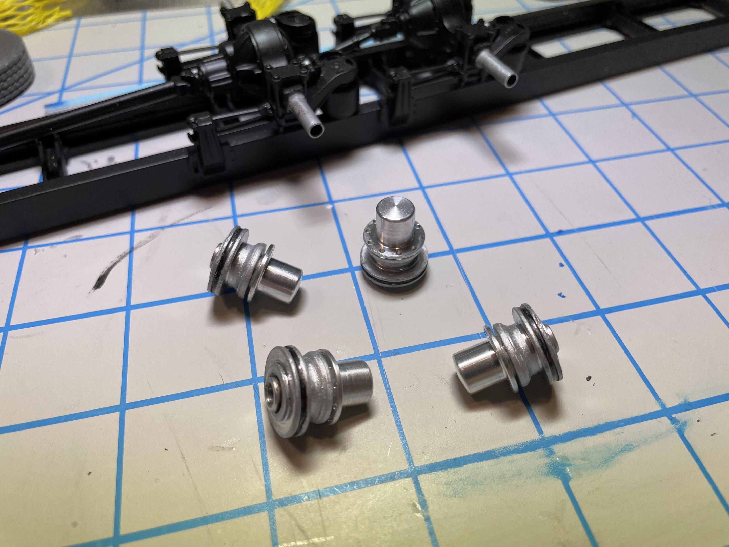
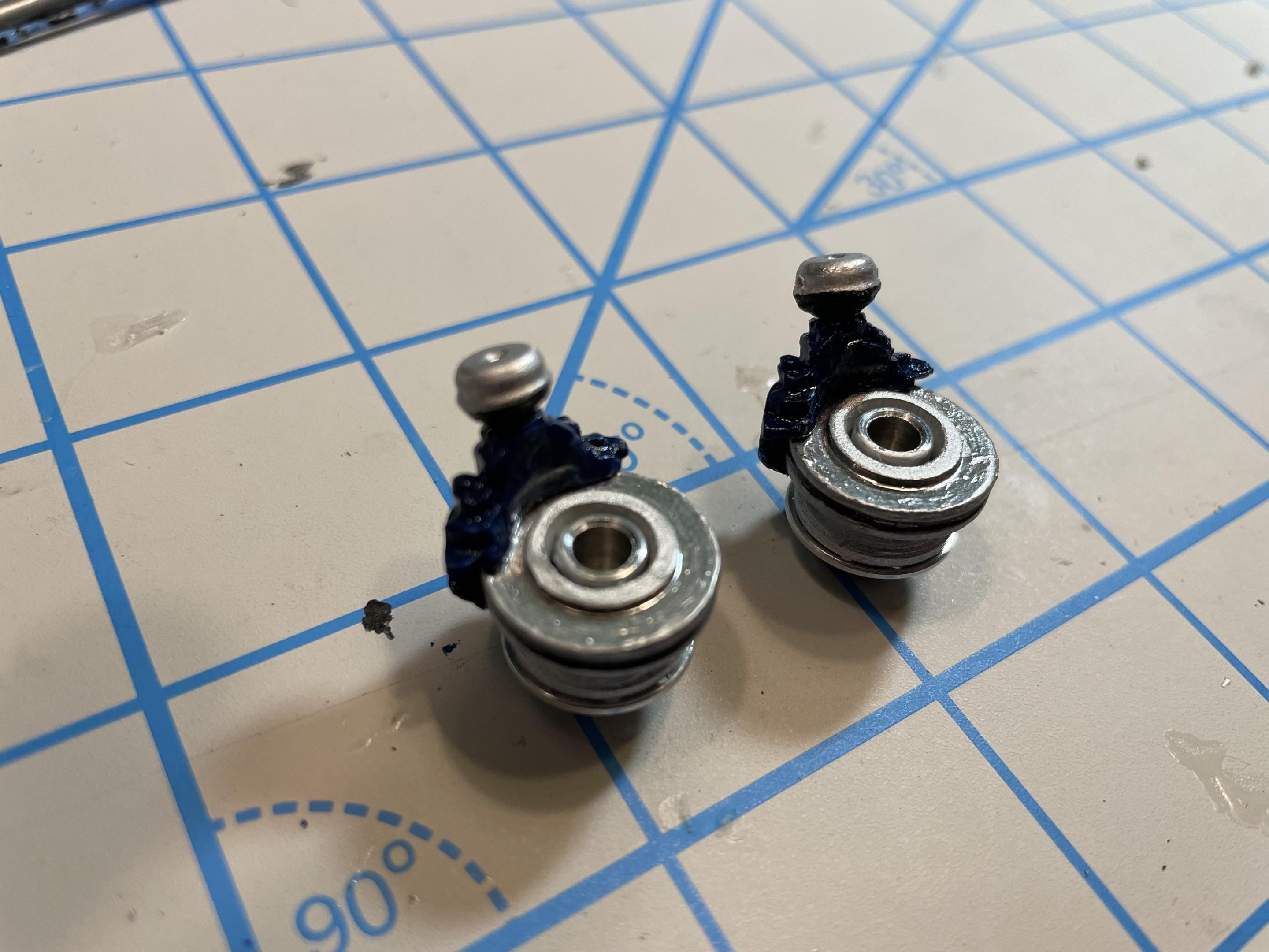
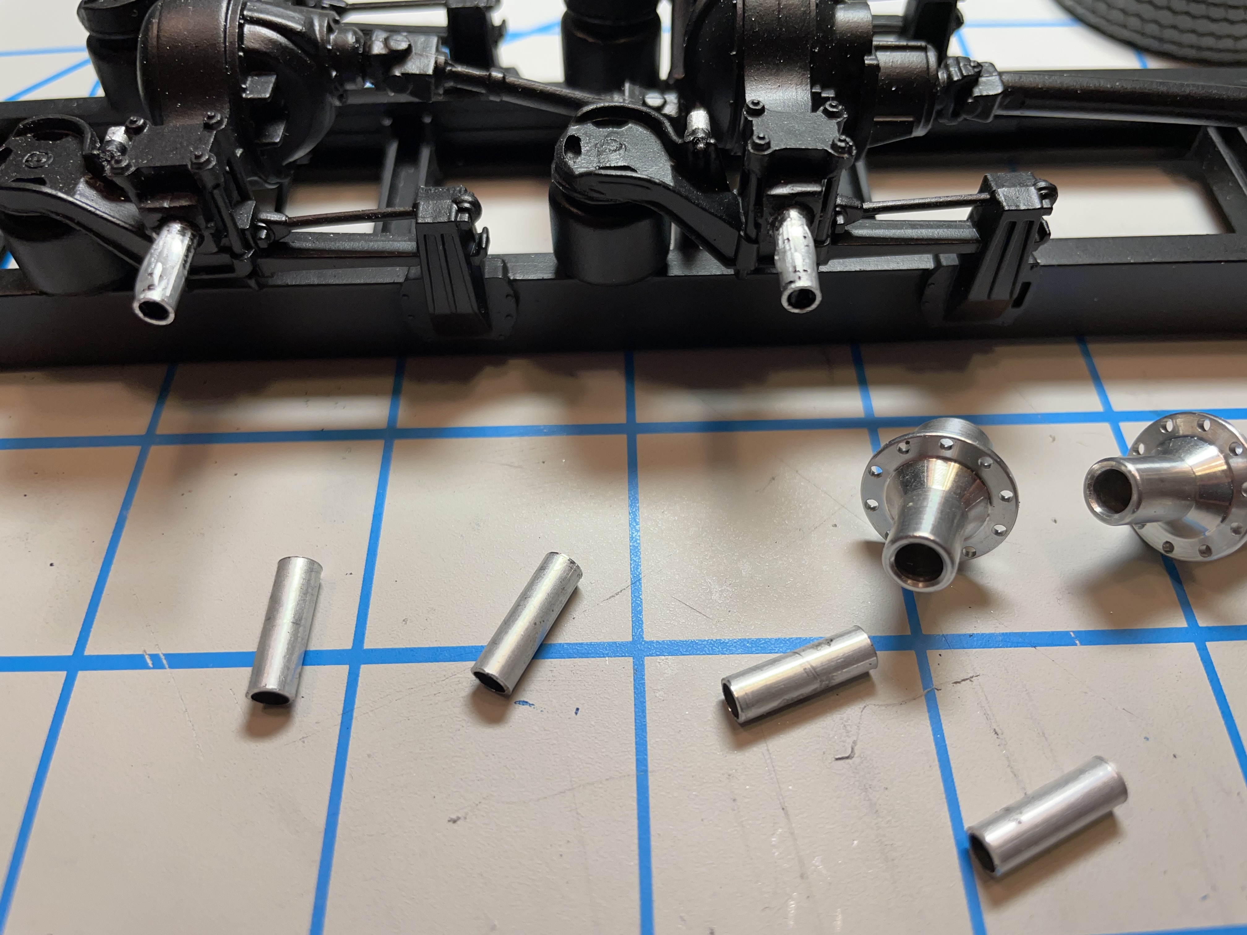
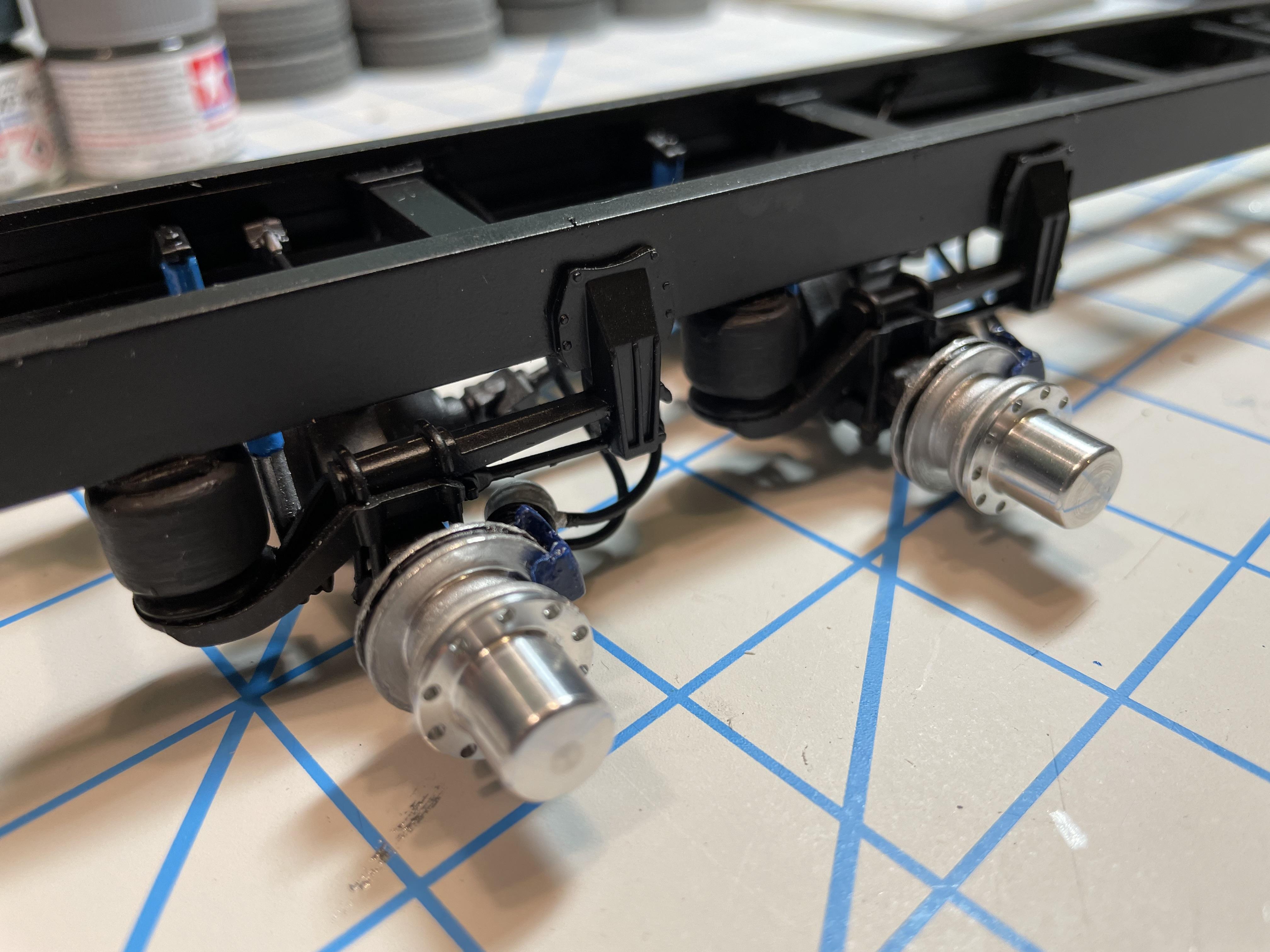
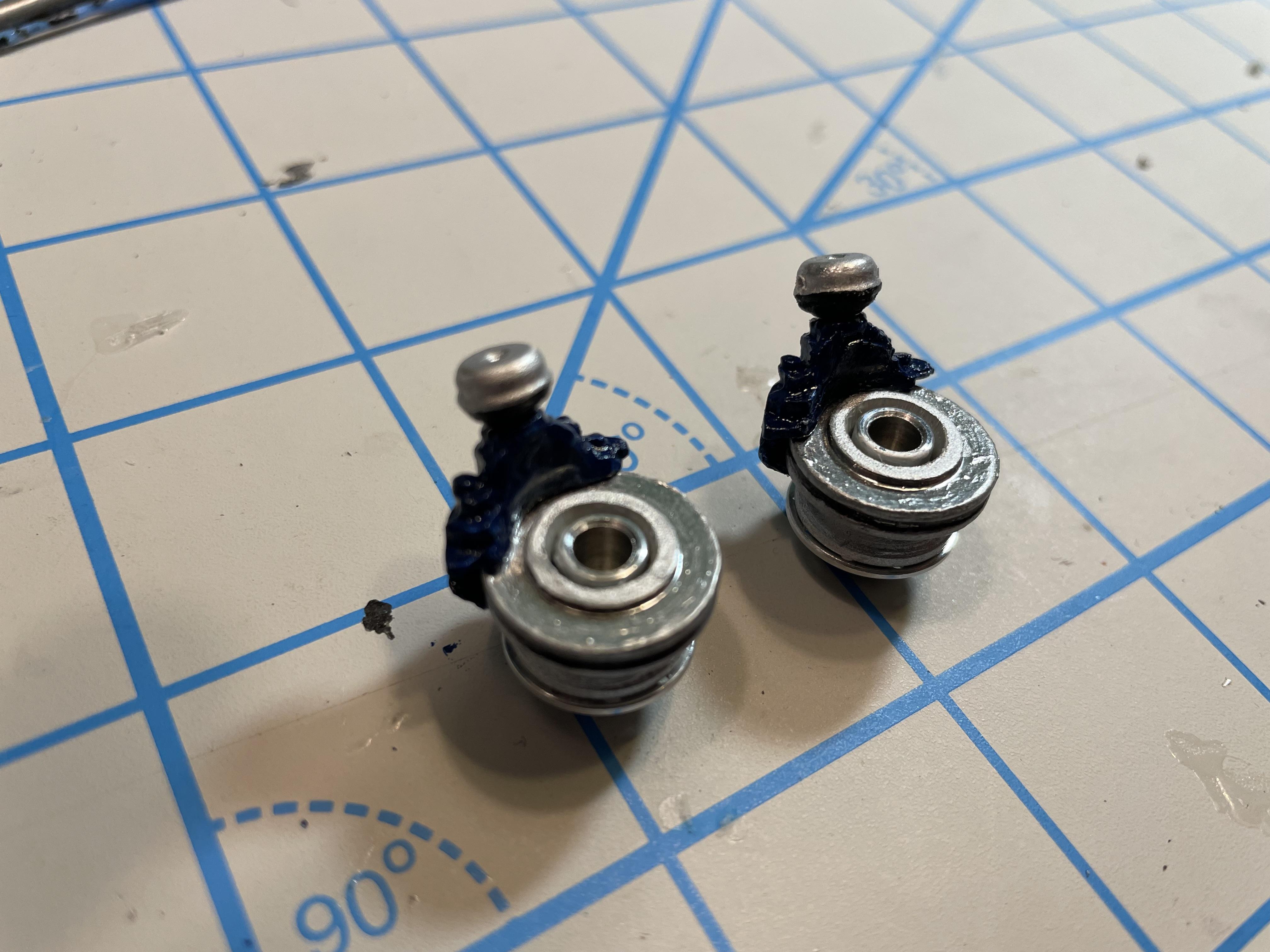
I added resin Bendix Air Disc Brake assemblies from Moluminum. Drilled them out to fit over the hub axle mounts.

I included air lines to the brake chambers, and ran the lines up to the frame rails. I didn’t bother running lines further than that, because, well, none of this area of the chassis will be seen on the completed model unless you turn it upside down. Not planning on that. The frame rails are mostly devoid of bolt detail for the same reason.
In fact, on the rear axles, all you’ll see is the outside wheels and tires. But, I guess when the build is finished, I’ll know the brakes and lines are there and that’s what matters. But, I sometimes have to ask myself “does it matter when you won’t see it?”
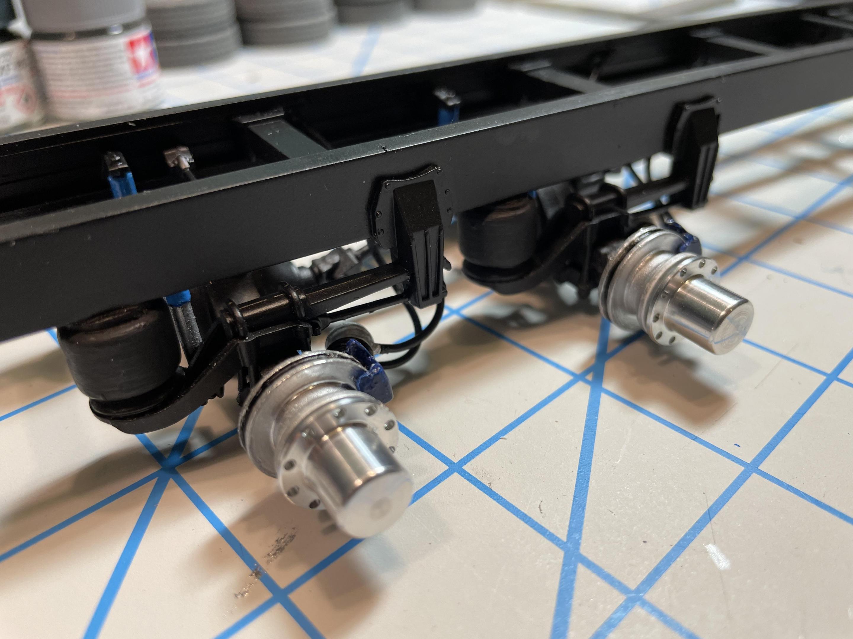
After all, this project has been about striking a balance between the sane and crazy, right?
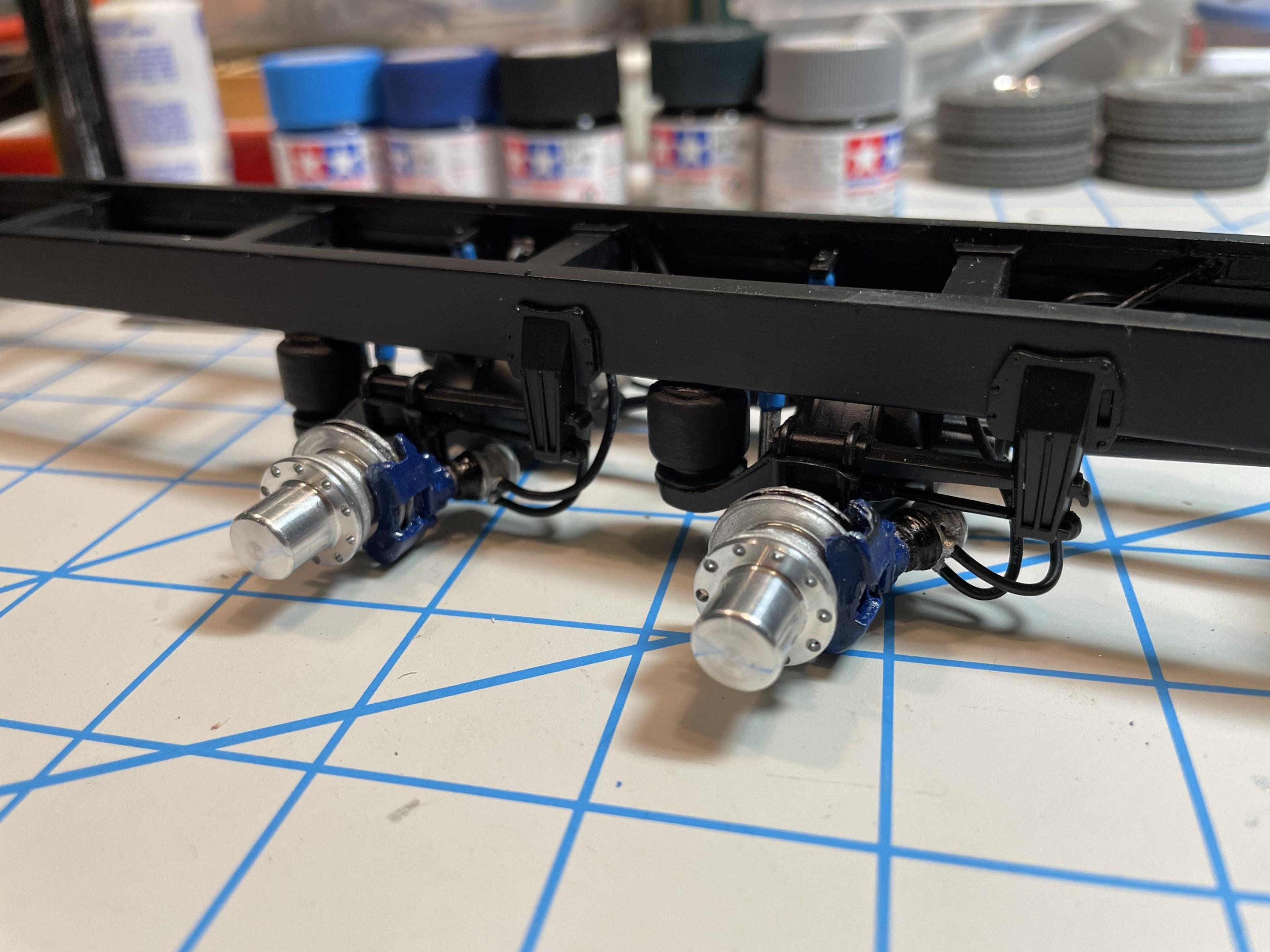
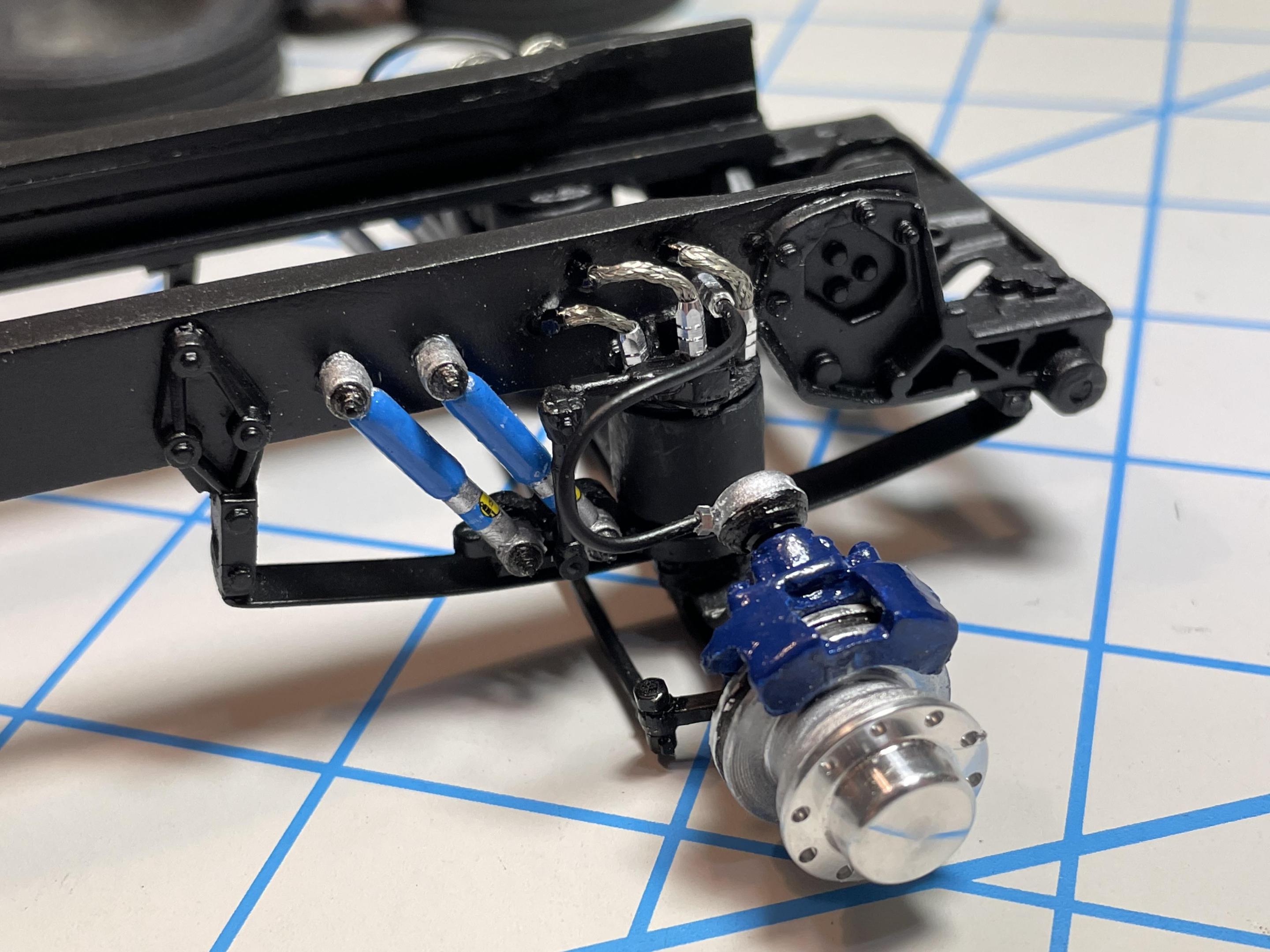
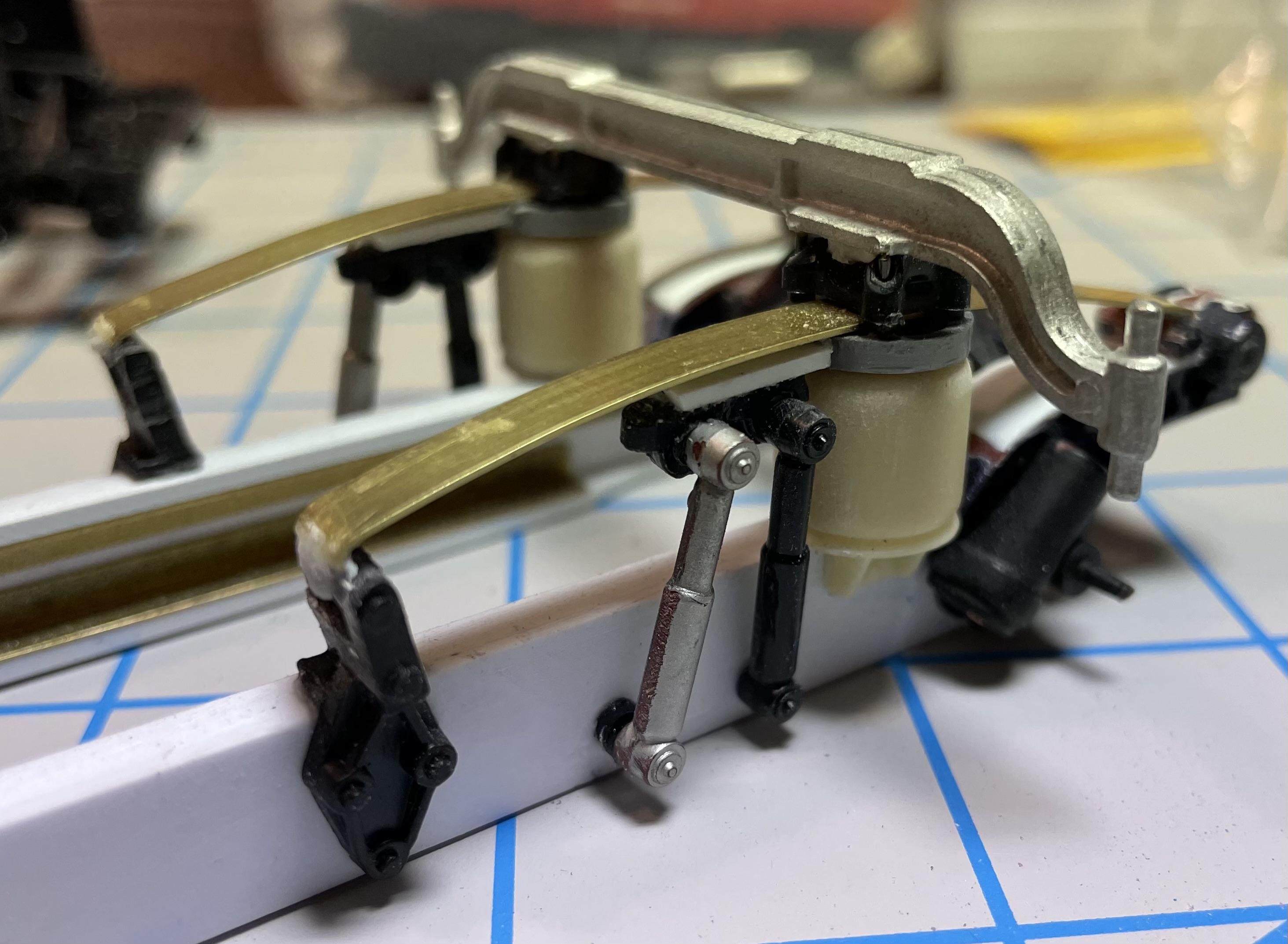
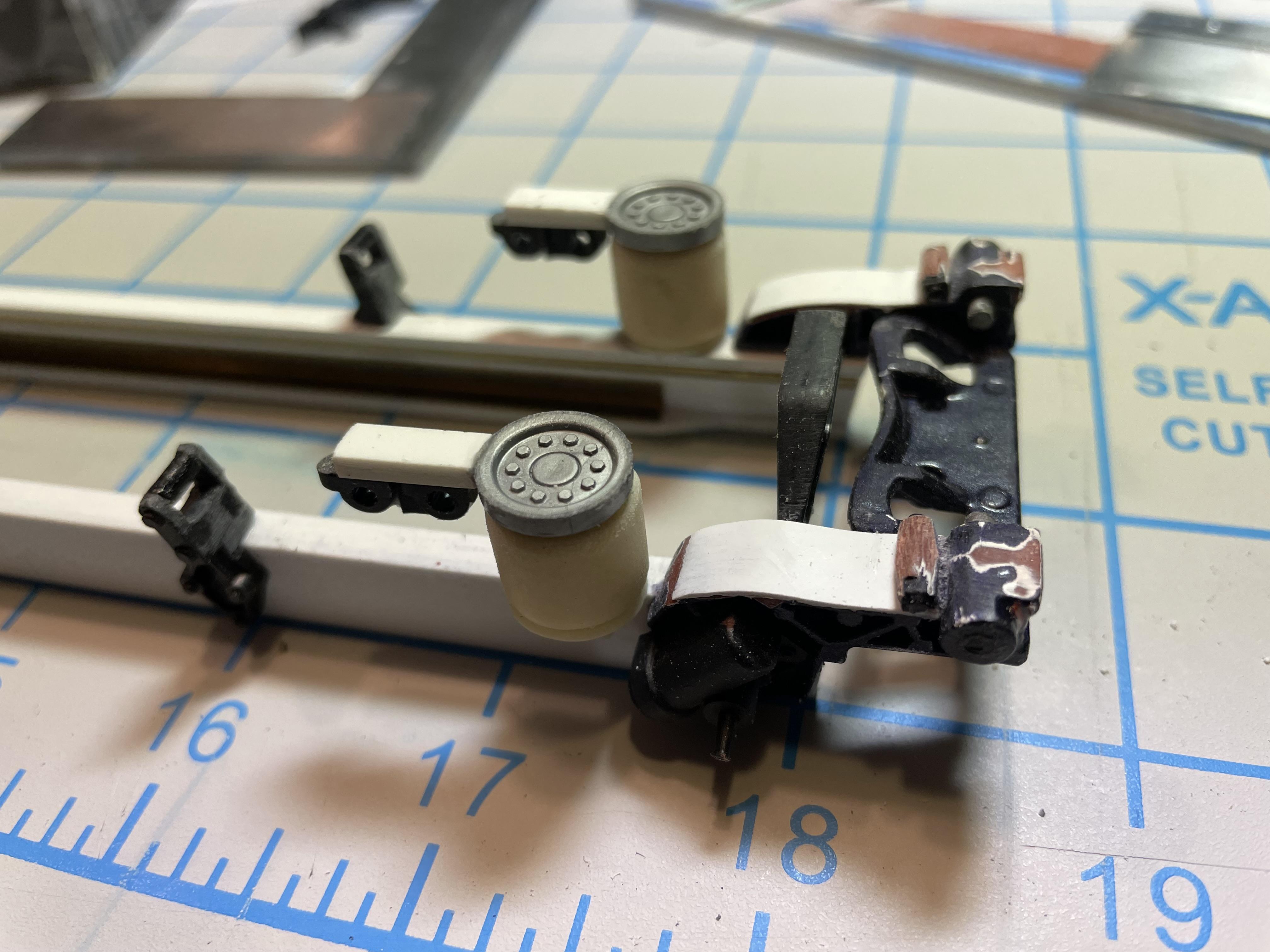
The front axle has disc brakes, too. I painted and decaled the shocks to represent Bilstein commercial truck and coach shocks.
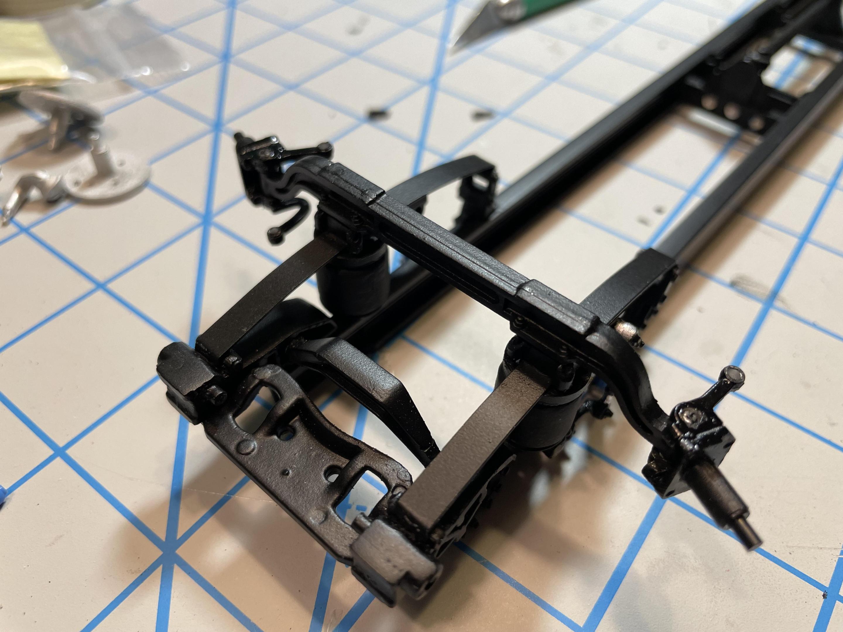
The front brake assemblies were also run with lines, along with the air bags. Air Bag Levelers were added using bits from the parts box. These details make more sense because they will be seen when you tilt the hood.
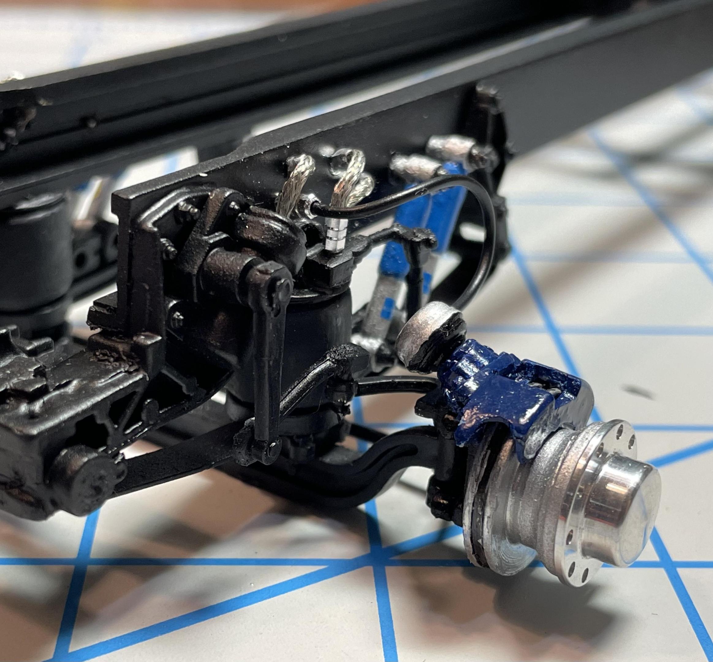
The air lines to the bags are braided line from Detail master with their fittings connecting to the mounts and to the frame rails. The resin air bags are brush painted in Tamiya rubber black. I opted to go with solid bags rather than rubber ones because of the potential amount of weight they’ll need to support.The hubs are fixed in place, not enabling the model to roll, though the front axle steering is functional. I like rolling models, but the vast majority of the time I glue the wheels in place because they can usually be positioned better (plumb and square) that way and they won’t roll off a shelf.
-
1
-
-
That’s a great build, and a set up you don’t see anyone model often. Nice. Welcome to the group!
-
Paint and finish looks great. Nice modification adding the stake bed, looks authentic.
-
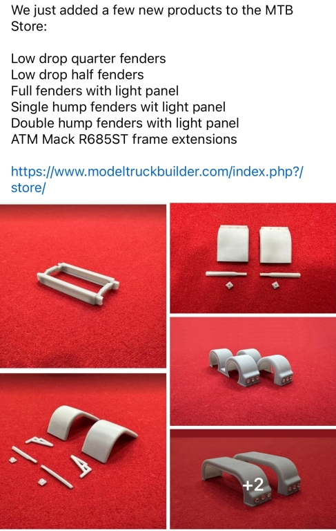
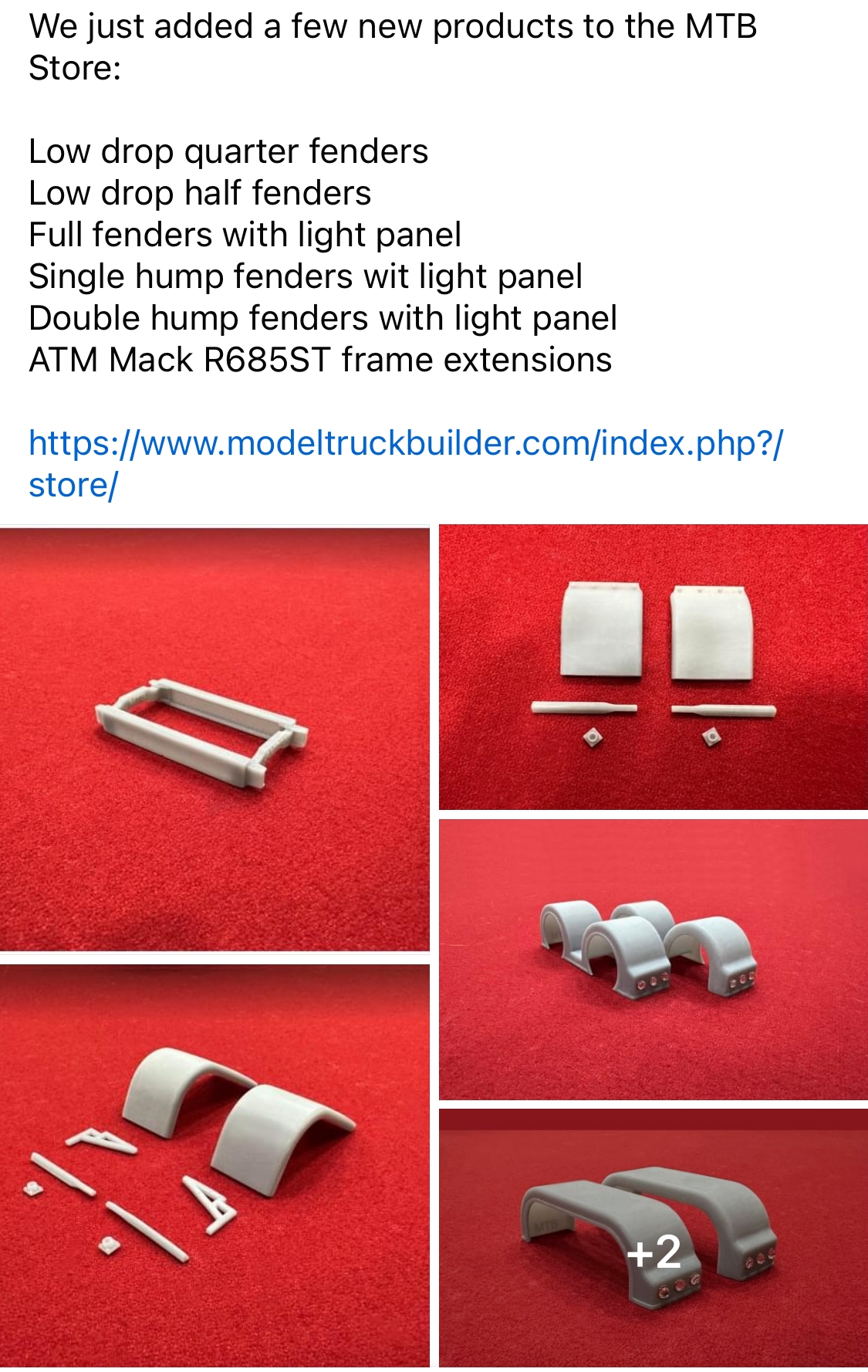
Several new parts are available. I’m glad the line of frame extensions has expanded. Keep ‘em coming!
-
Daycab or kit sleeper?
-
1
-
-
21 minutes ago, Gary Chase said:Wow, nicely done, love the front suspension and details
Thanks! It’s been a good learning process.
-
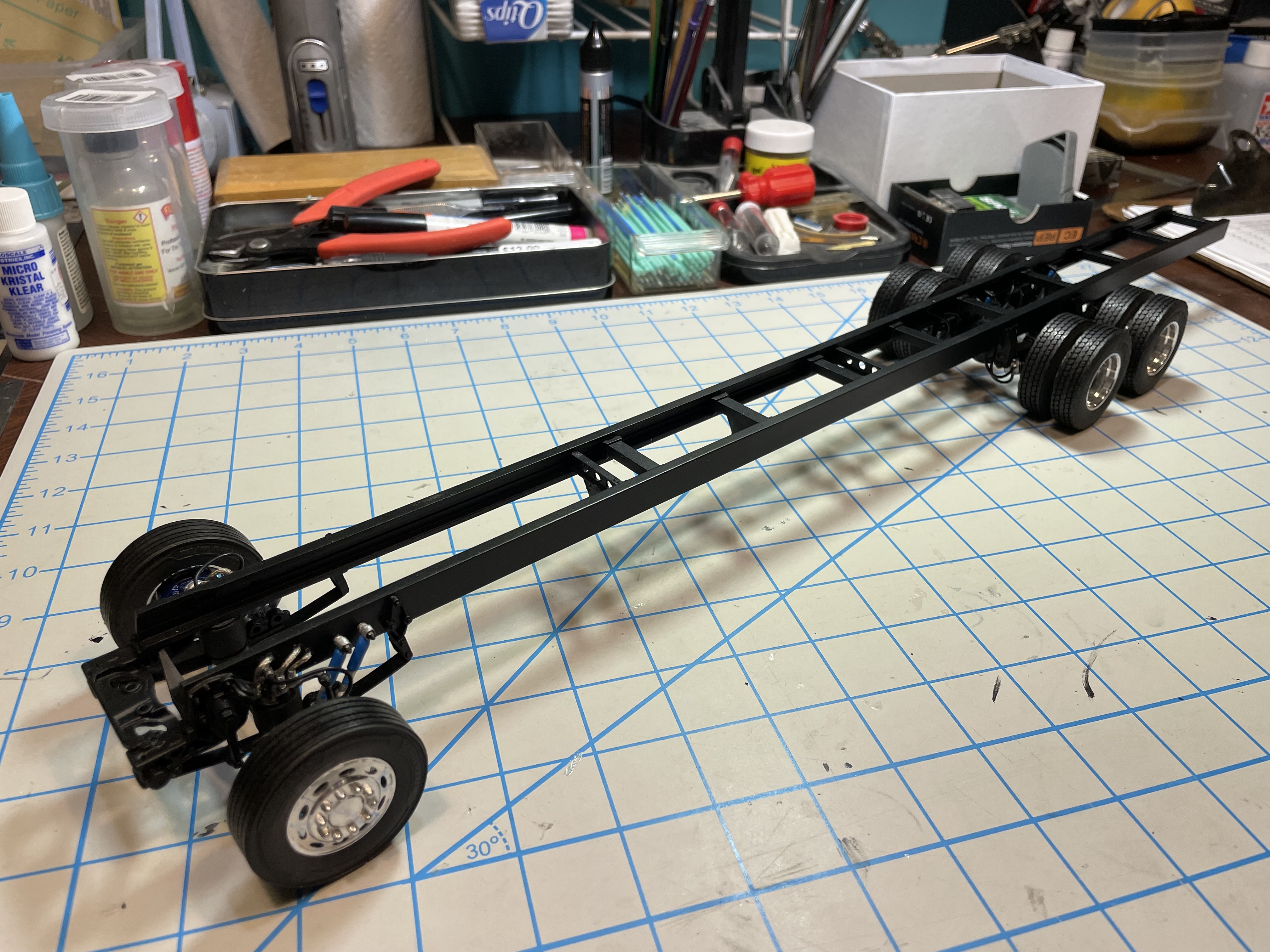
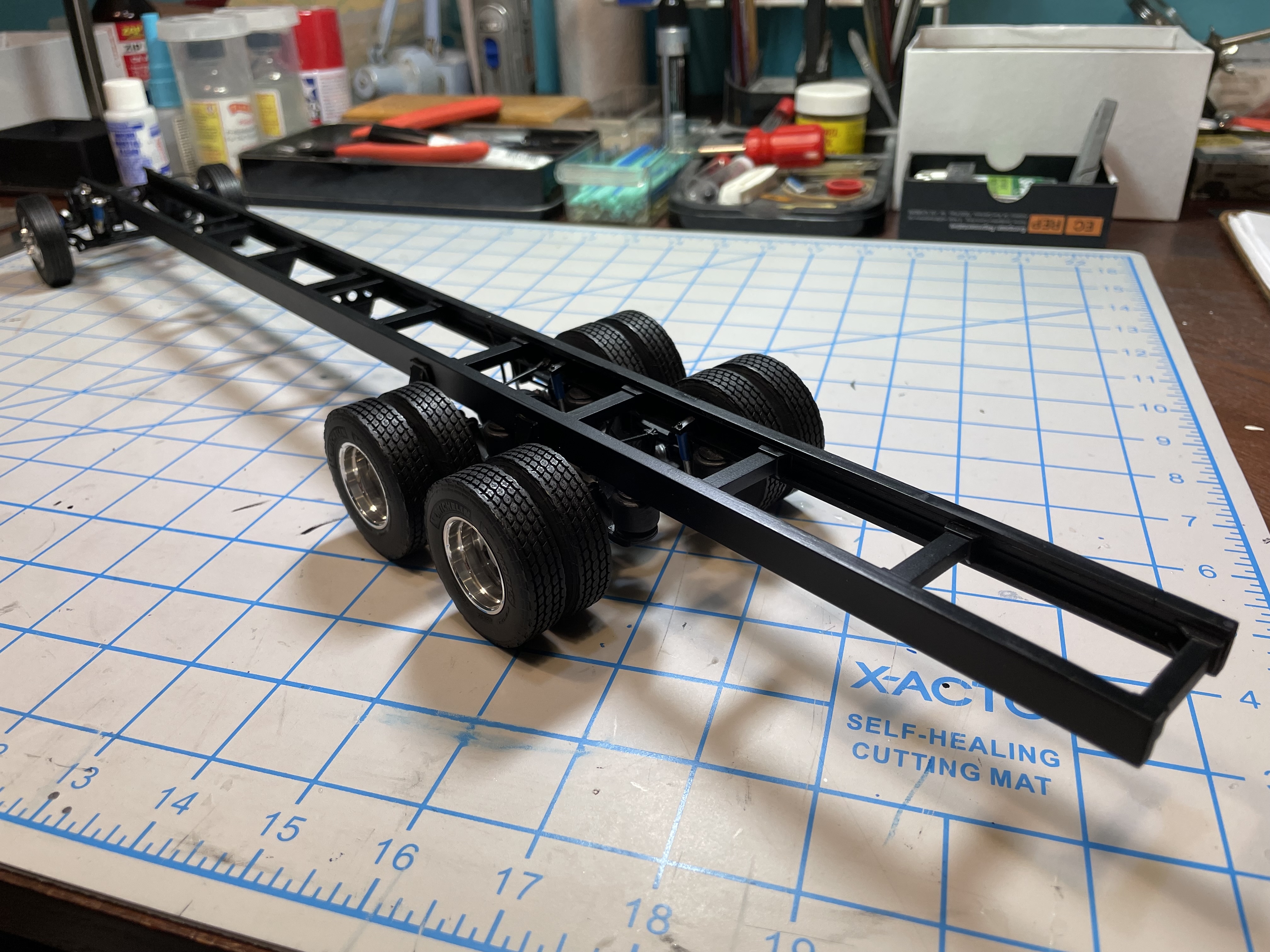
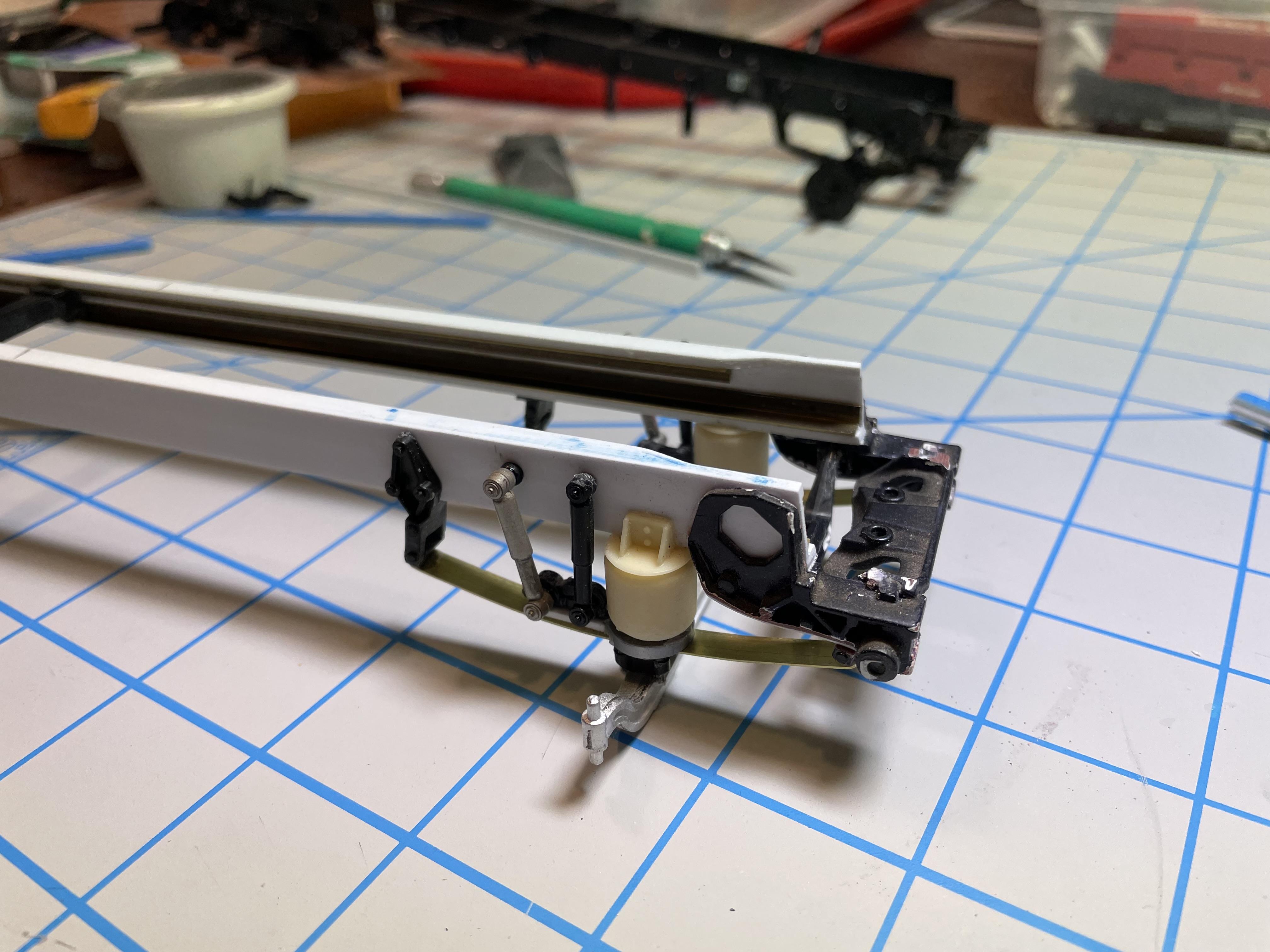
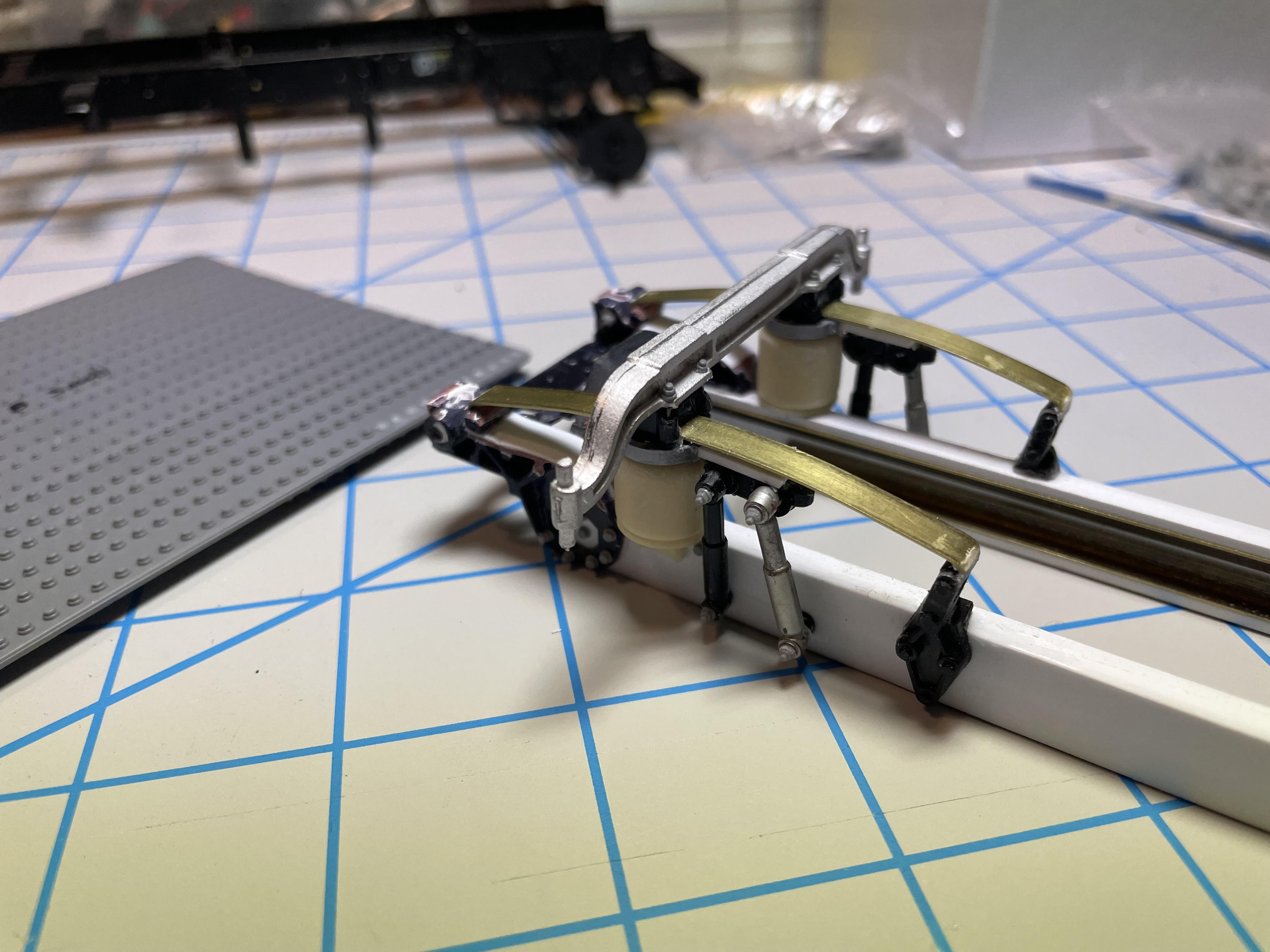
Next up is the chassis. Factoring in the length of a scale 45’ rig, I wanted a strong frame, even though the RV body itself will provide a source of support having it’s own framework, but I didn’t want to risk it. Since I’d have to stretch a factory frame so much anyway, I figured a fully scratchbuilt, one-piece frame would be easier to make in the long run - and stronger, too.
I scratchbuilt the frame rails with styrene strip/sheet and added brass angle to the inside corners. No flex.
The frame rail material is thicker than the stock Italeri 378 frame rails, so I had to modify the ends of the Italeri crossmembers to fit inside the new rails.
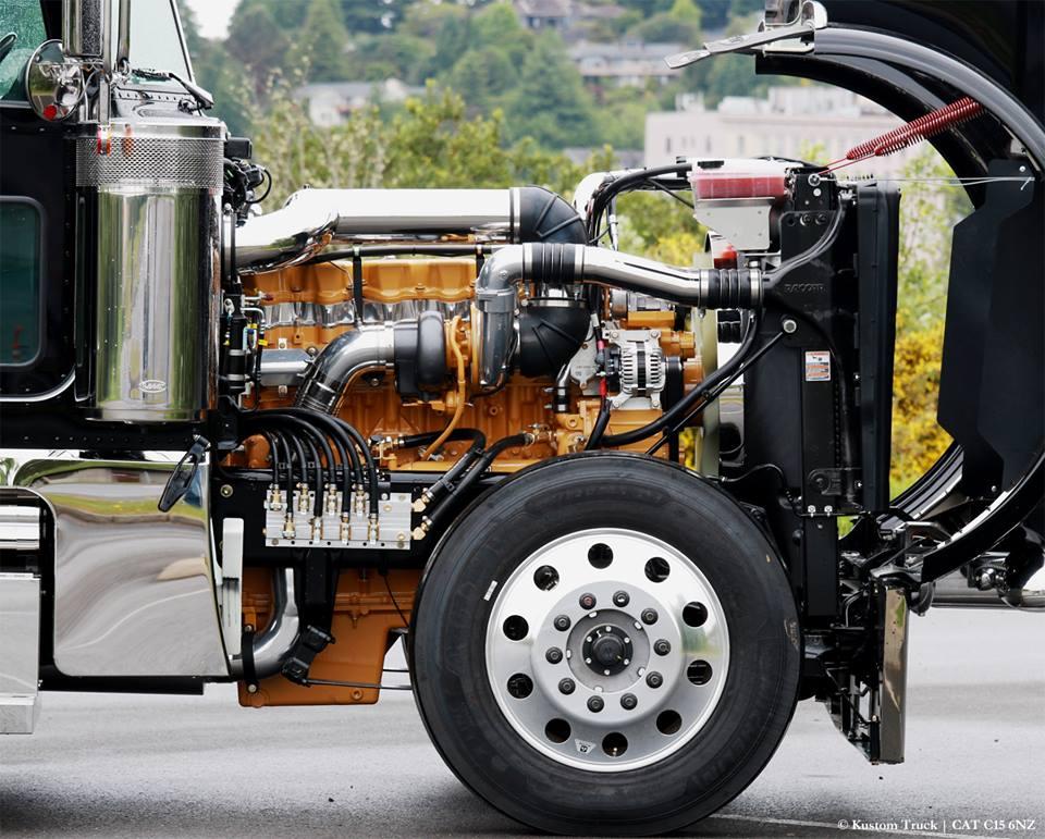
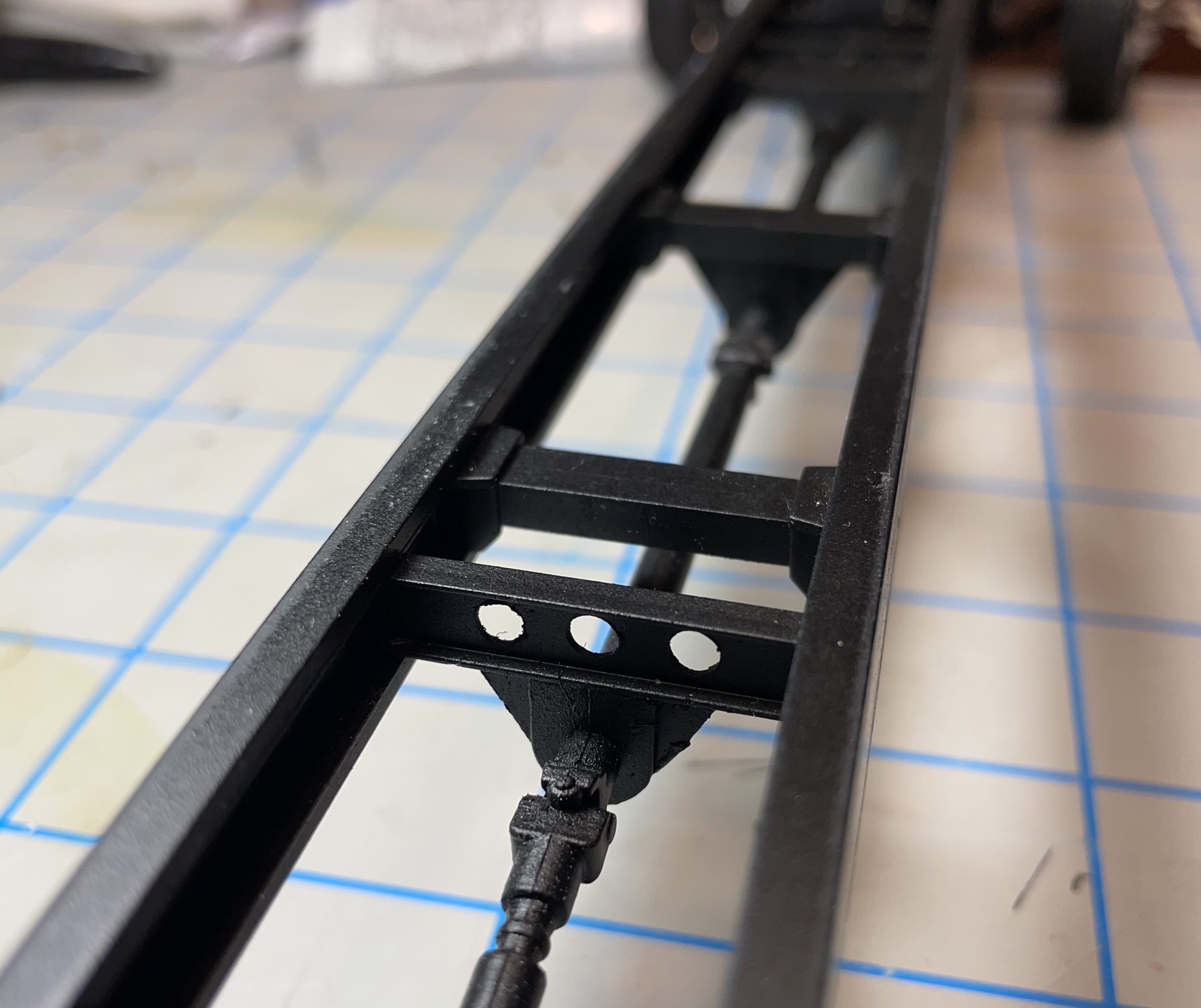
I then began work on the front axle and suspension. I wanted to model an air ride front axle with a 16k capacity. Here’s a photo of a 1:1 Pete 379 upfitted with an aftermarket air ride front axle.
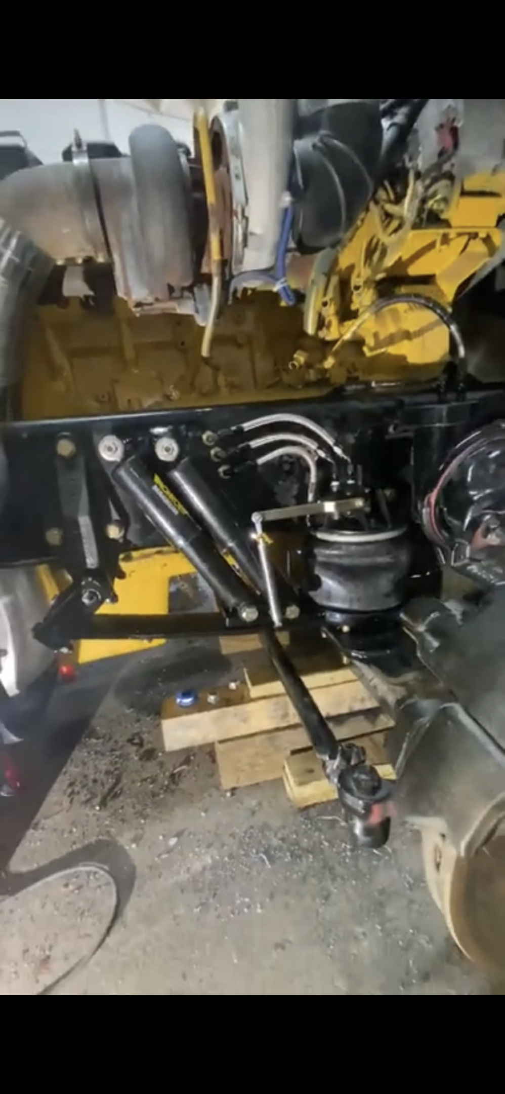
Like the photo above, the build represents a retired Pete 379 that’s been retrofitted with a heavier axle and aftermarket suspension during the conversion to an RV.
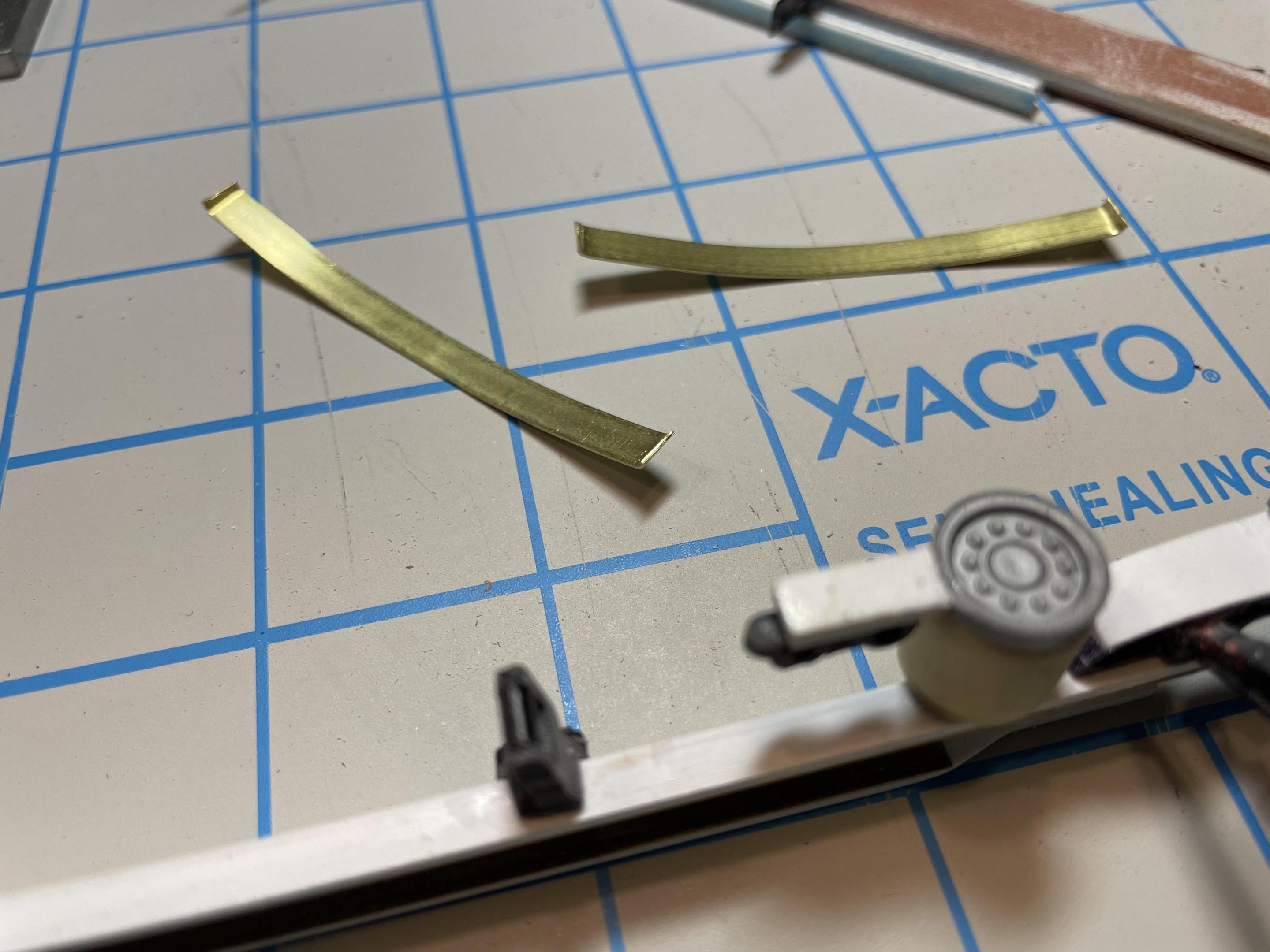
I used 3/16” brass strip for the single leaf spring, auslowe resin air bags and components from the parts box, along with parts from a glue bomb Italeri 378 - old parts getting a new lease on life, just like the real thing.

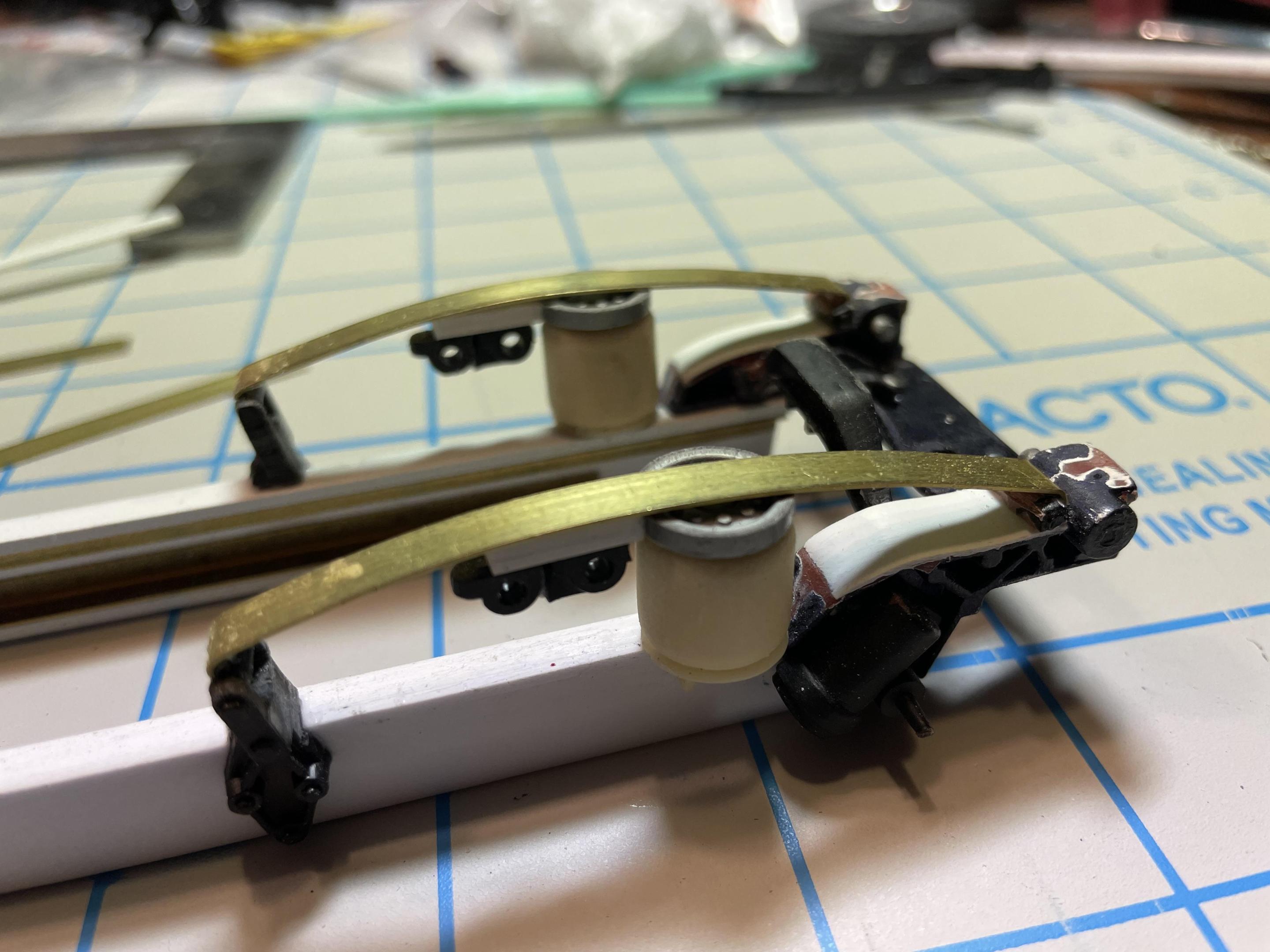
In the photo above, you see the shocks in a slightly different position than I ultimately decided on. I later changed the angle to match the 1:1 inspiration photo in this post.
Spring hangers are from the Italeri kit. On the theme of a sturdy frame, I added a metal front axle from Auslowe.
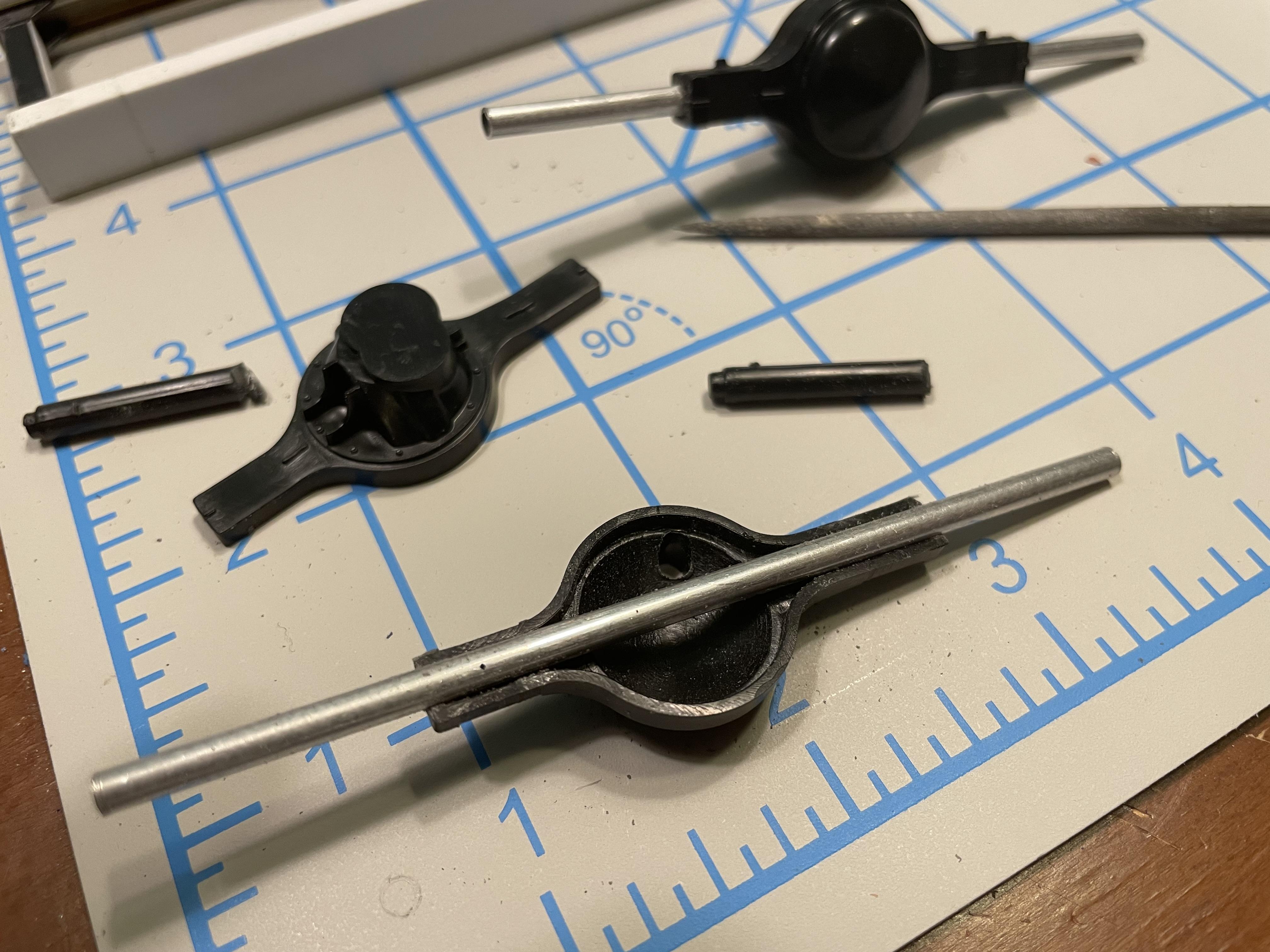
For the Italeri rear axles, I cut off the ends and I carved out the inside a little to be able to insert metal tubing to make them stronger.

Here the tubing is way too long, but I later cut the tubing to match the width of the original kit parts.
I added some bolt head detail to the front area, but most of the frame rails are smooth with no added detail as they will be pretty much hidden when the body is added.

-
5 hours ago, Johnny M said:Vincen47,
2 things:
1. Wow ! Your engine looks beautiful 😎
and
2. What other forum you talkin' bout?
Johnny
Thanks! The other forum is the Model Cars Magazine Forum. It’s not specifically focused on trucks, but it has some truck-only categories.
-
1
-
-
Just in case some of you are not on the other forum, I thought I’d start a WIP thread here, too.
It is an usual project, but these rigs are becoming more and popular in the race and general RV travel markets, so you may have seen them on the road…
Imagine taking a retired truck and building your dream RV from it?
This build will be mostly custom work, just like the real thing. These rigs don’t roll out of the ‘ol Winnebago factory…and you find models like this in a kit, either.
I will use Italeri’s 378 for some parts, along with Bill Drennan’s 379 hood. Lots of scratcbuilding and a host of aftermarket parts.
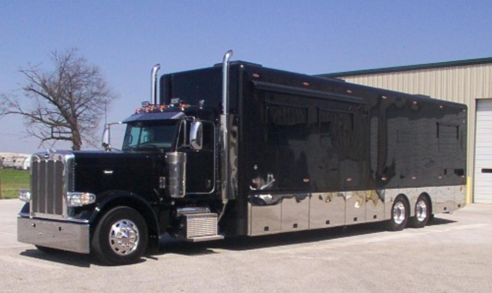 Inspiration for this project came from rigs like this, (though the one above is a 389) where a used or factory-fresh commercial class 8 chassis is stretched and a coach body is added, creating the ultimate RV.
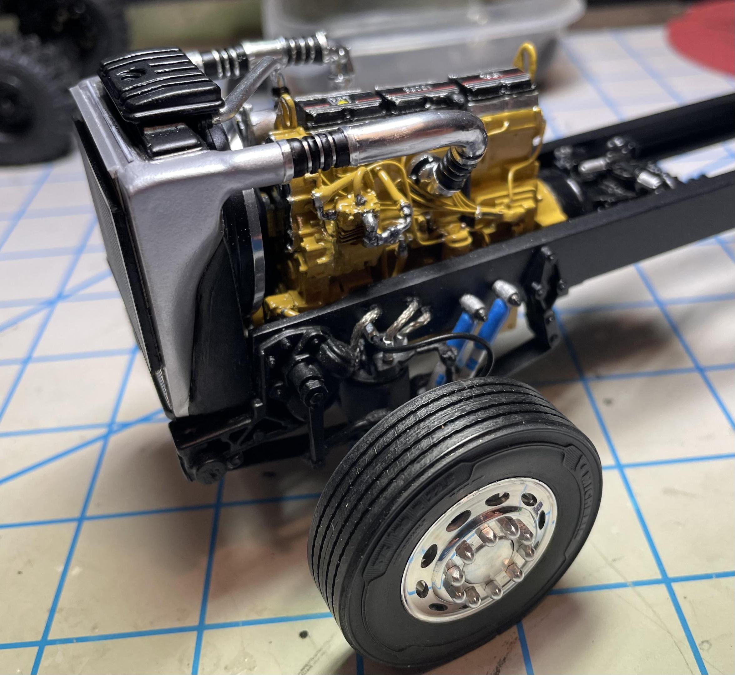
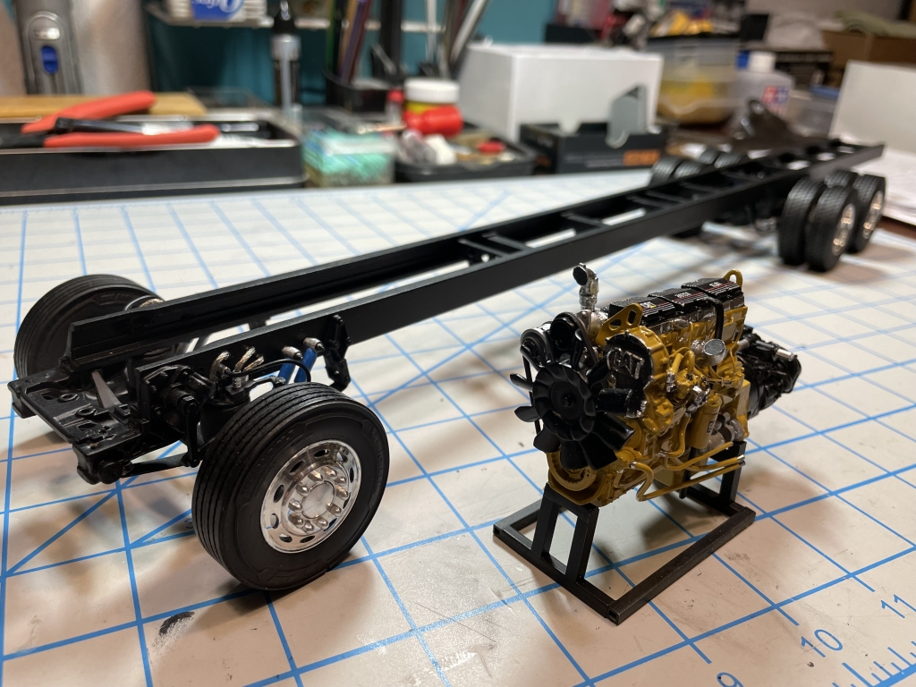
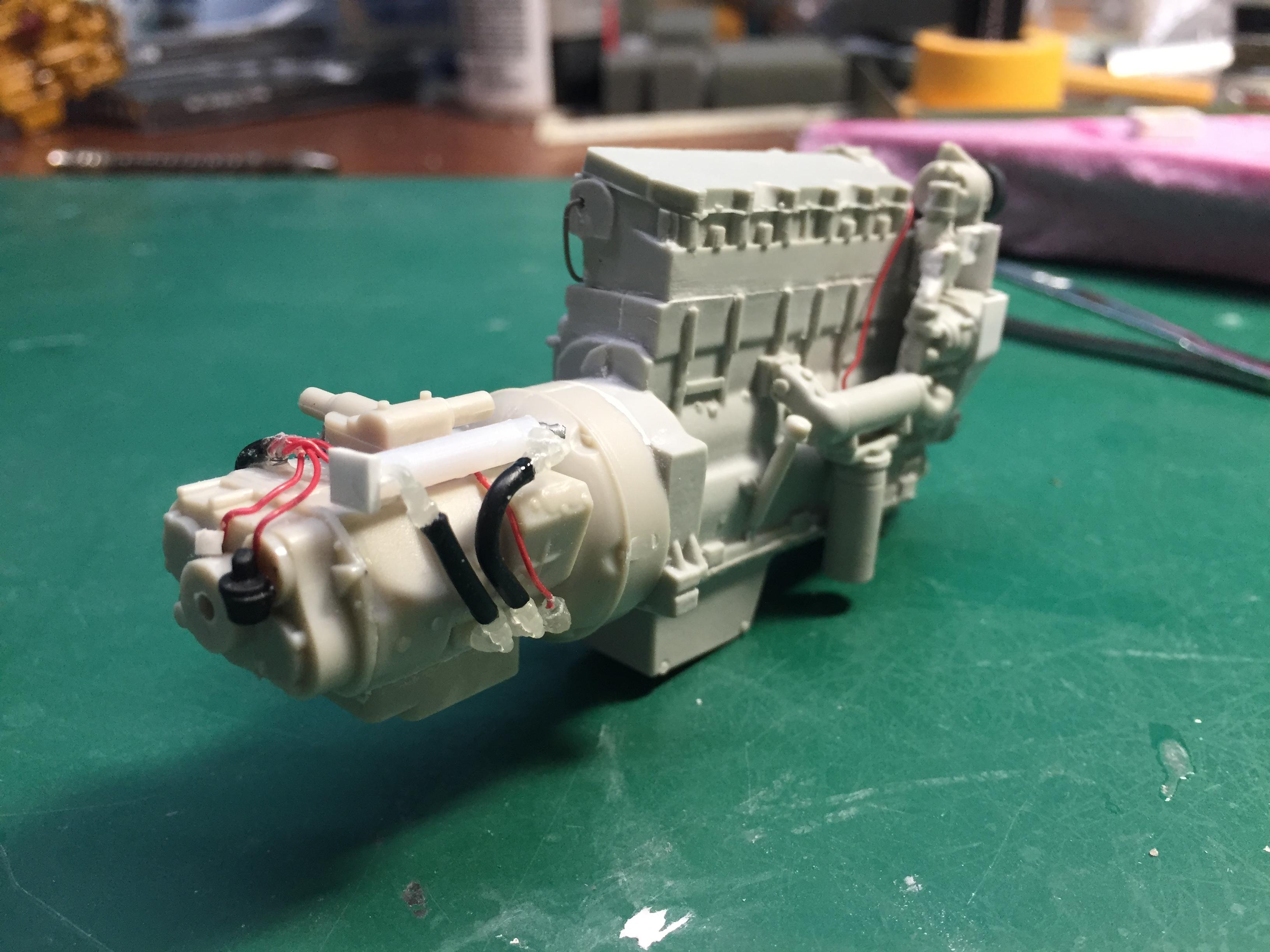
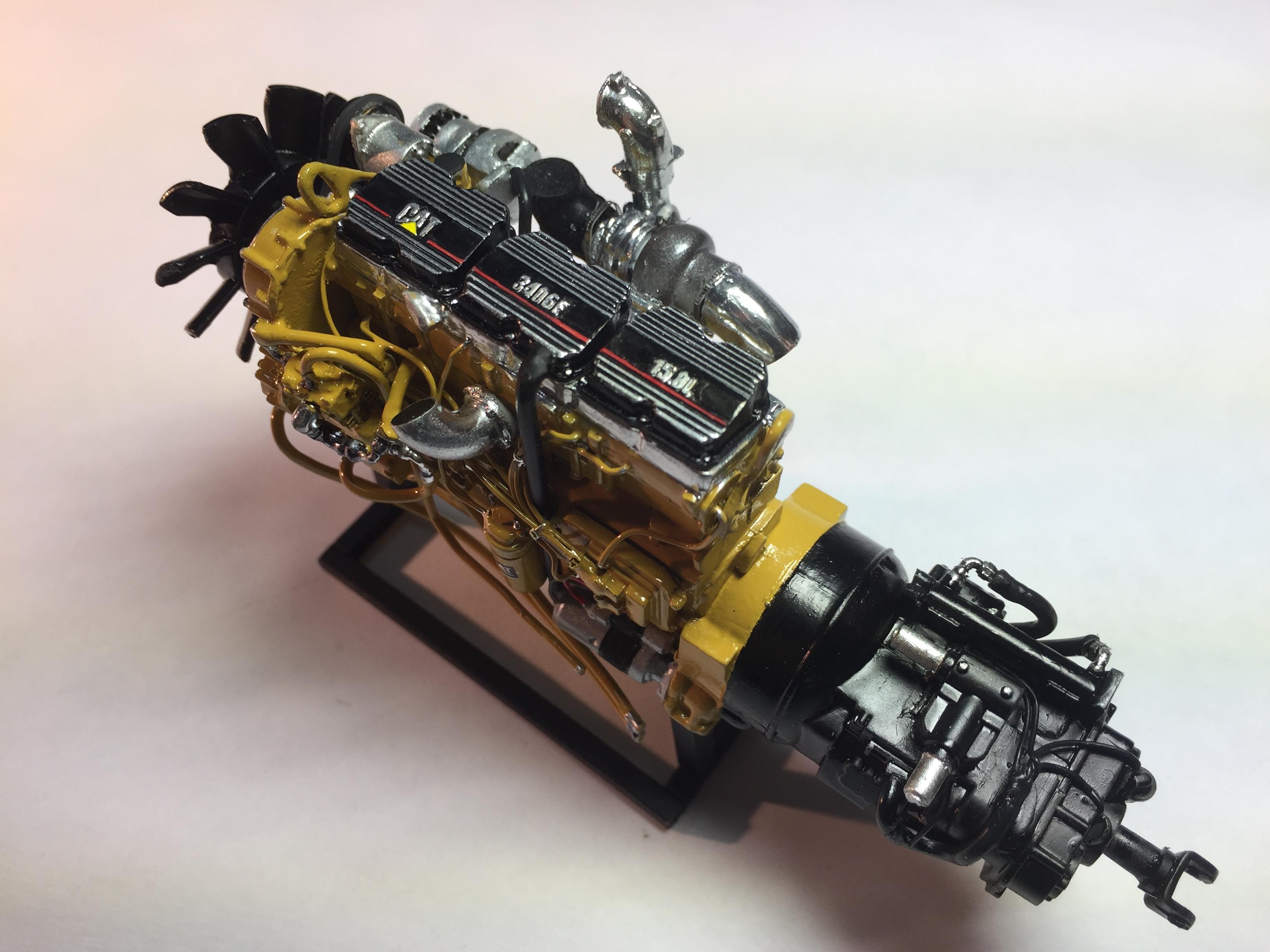
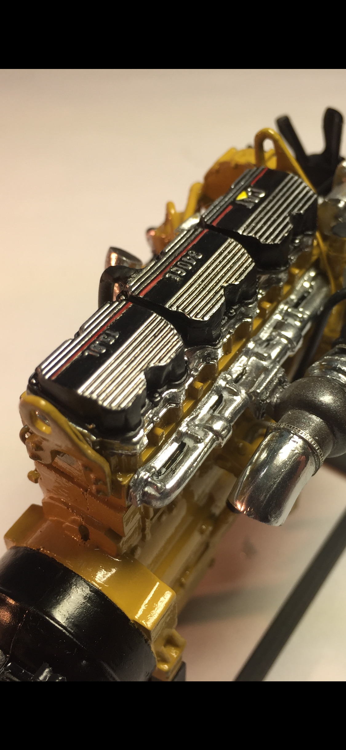
The ultimate RV starts with the ultimate engine. Some may argue differently, but I think Cat’s 3406e from the late 1990’s is the finest example of diesel power, especially when it’s been decked out in aftermarket chrome and ceramic performance parts.
I started with a resin Cat 3406E from Jamie at Moluminum. I detailed it using Ken Smith’s Car Modeller article on Fotki. I used 3d printed elbows from modelbuildermatt on Shapeways and metal fittings from Detail Master.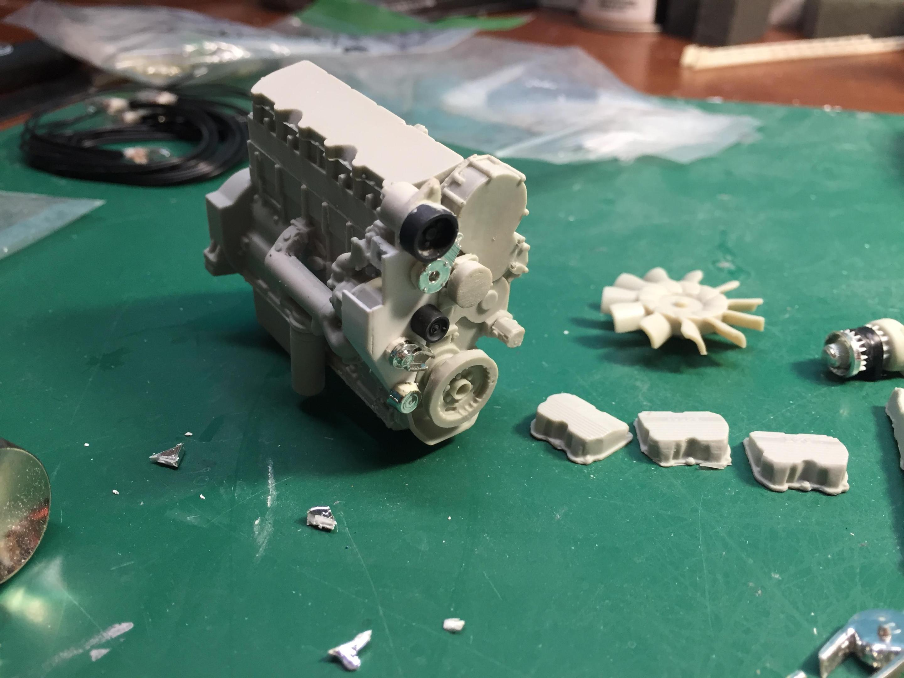
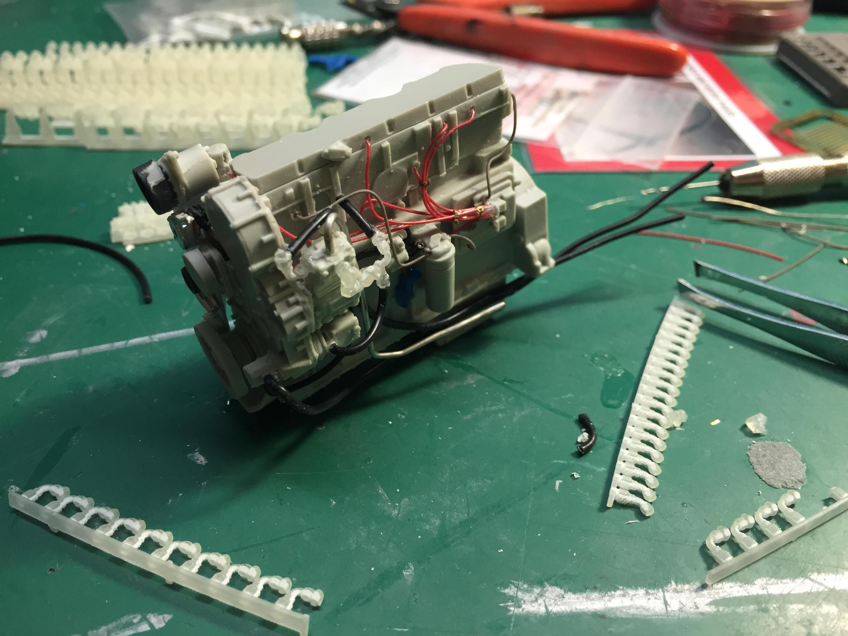


Several engine components were scratch-built. The 18 speed Eaton Auto-shift transmission came from Moebius, with a lot of detail parts added using reference photos.
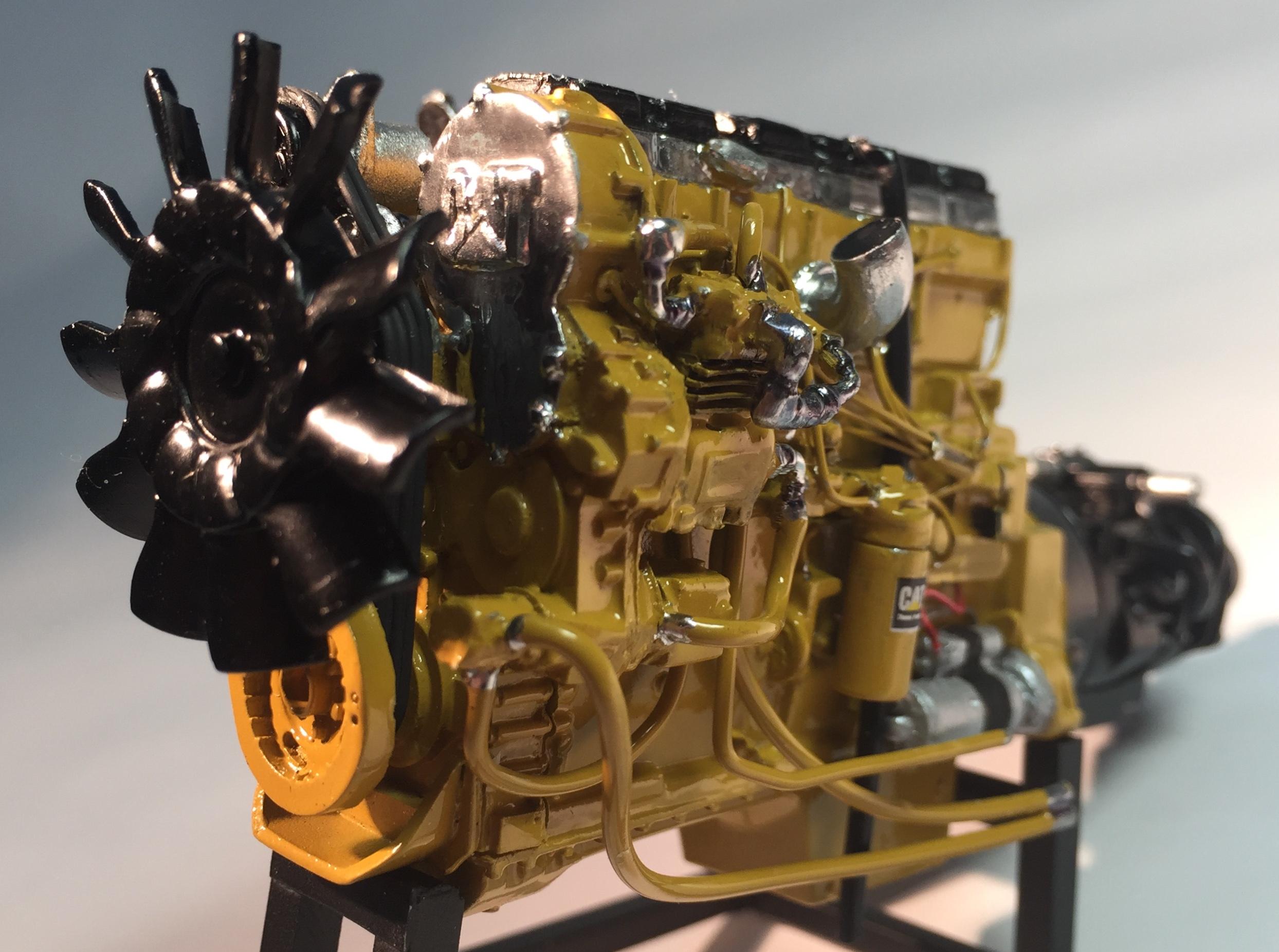

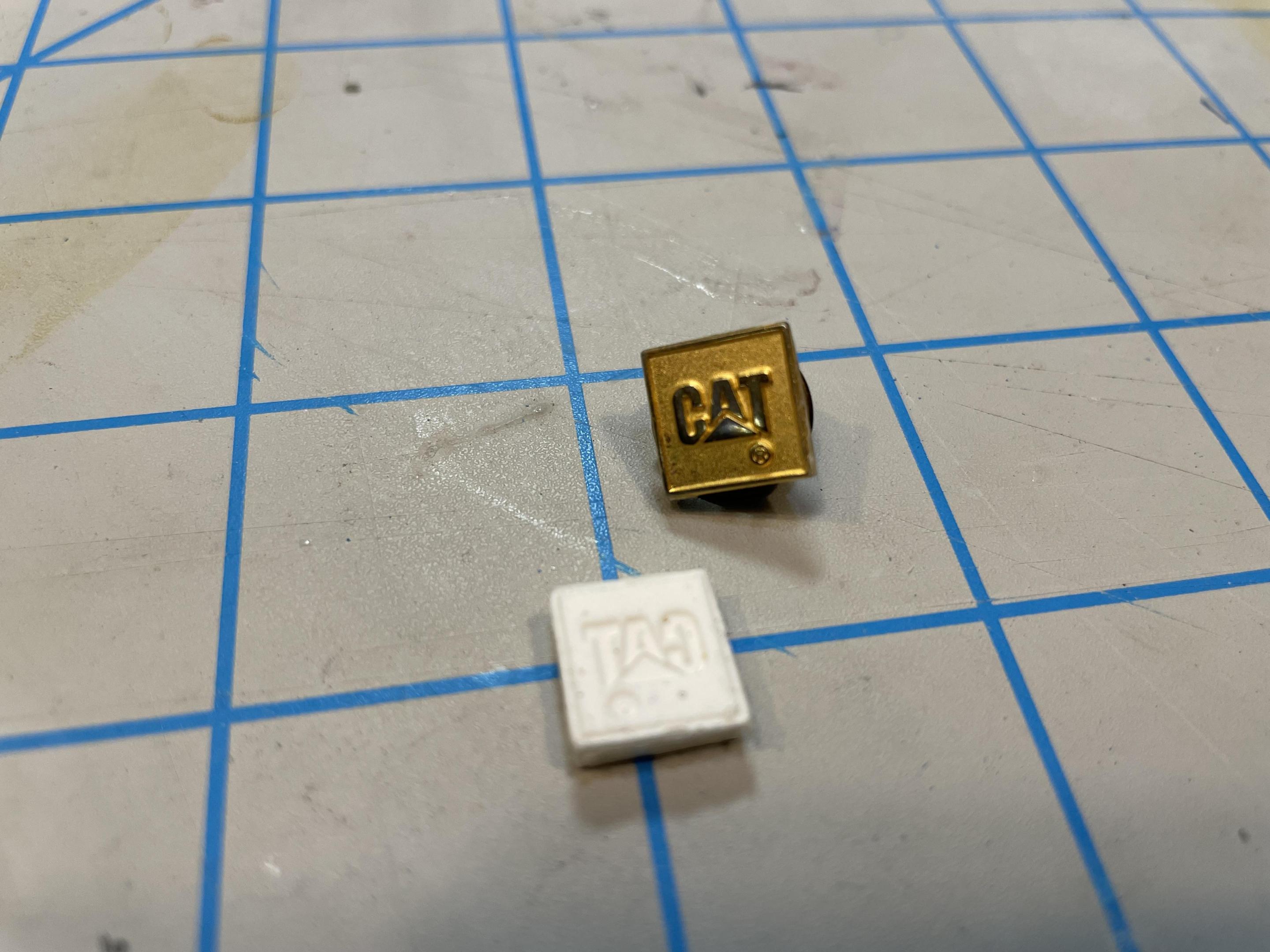
Jamie’s casting didn’t include the 3 dimensional “CAT” logo on the chrome timing cover, but I added one using a casting of a Cat lapel pin I found on EBay that was the perfect size. I’m not a pro resin caster by any means, but I’ve found casting small, very simple parts, to be useful in this project.
 It took me several attempts, maybe a half-dozen, to get the valve covers looking good. I finally found putting Molotow down first, then adding the black in the recessed areas via a Molotow black pen was best. Careful painting of the red stripe and a triangle-cut of a yellow decal finished the iconic look of the Caterpillar 3406e’s valve covers.
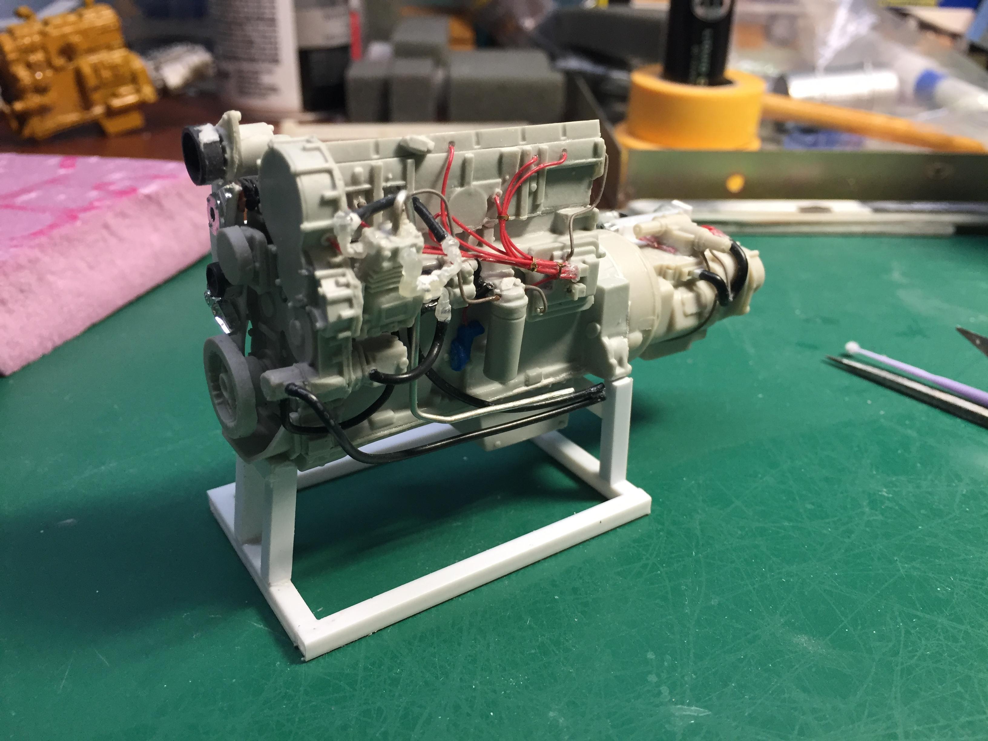
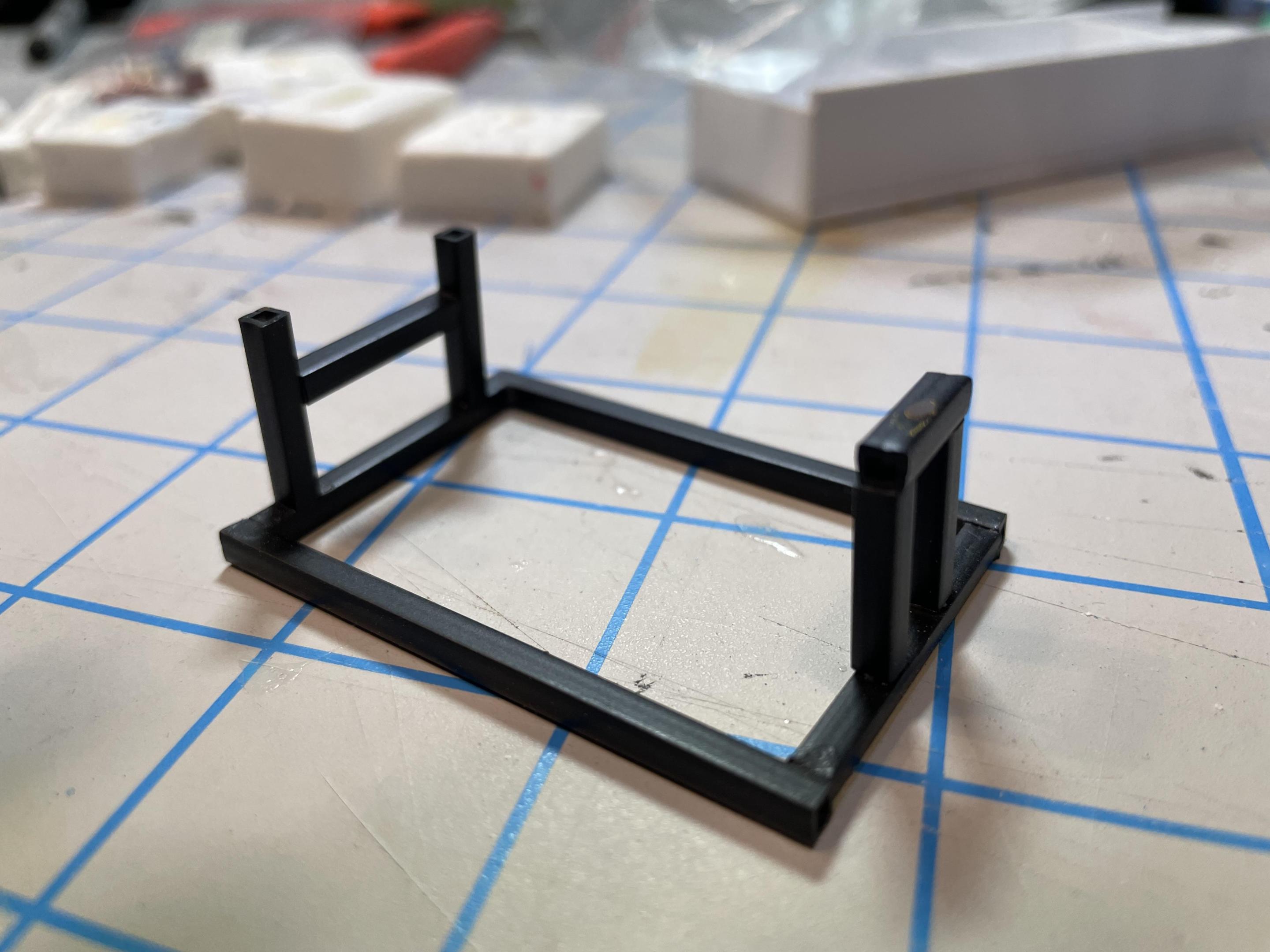 I put together a simple engine stand using square styrene tube. I currenty use it for other engines that are waiting to be installed in the next chassis. It’s a handy tool.
That’s the basic engine so far, more about the other engine components when we get to the chassis installation. Ask questions, I’m sure there’s explanations I missed.
Next, let’s get the frame rails laid down…
-
1
-
-
2 hours ago, Gary Chase said:They do in pictures, I will post up how the fit, quality and adjustments when I get them.
I haven’t ordered anything from them yet, so I’m looking forward to your opinion.


Autocar A64B
in Model Truck Show Room
Posted · Edited by vincen47
That’s a beautiful truck. Makes a great resto-mod. Maybe gets some work, but nothing too hard in its semi-retired life, and always gets cared for, washed and polished. Maybe it’s the boss’ truck, something you’d see at a truck show. Nice work.